Image forming apparatus

a technology of forming apparatus and forming roller, which is applied in the direction of electrographic process apparatus, instruments, optics, etc., can solve the problems of excessive temperature rise of non-passing region not contacting with recording materials in the heating roller of the fixing device, and the insufficient exhaust of the apparatus

Active Publication Date: 2007-12-06
CANON KK
View PDF4 Cites 36 Cited by
  • Summary
  • Abstract
  • Description
  • Claims
  • Application Information

AI Technical Summary

Benefits of technology

[0013] The present invention is directed to an image forming apparatus that c

Problems solved by technology

Such image forming apparatus is often accompanied by technical problems.
As a second problem, in the recording material receiving heat, when sheets are discharged and stacked continuously, sheets are adhered to each other between the face and back side of the recording material.
When recording materials with smaller width than the maximum width are fixed continuously by the fixing device, the temperature of non-passing region not contacting with the recording materials in the heating roller of the fixing device is raised excessively.
In this structure, the air from the cooling fan for cooling the recording materials and the air from the non-passing portion fan for cooling the heating roller are converged and exhausted out of the device, but if the flow rate is excessive, exhaust may not be sufficient.
When such air returns to the conveying path before f

Method used


Image

  • Image forming apparatus
  • Image forming apparatus
  • Image forming apparatus

Examples


Embodiment Construction

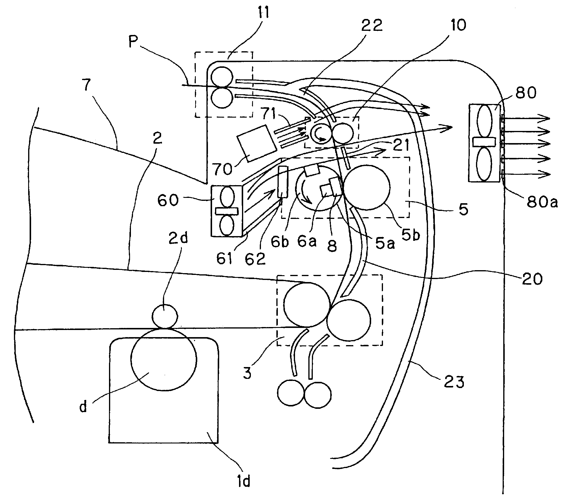
[0021] An embodiment of the invention is described below with reference to the accompanying drawings. Throughout the drawings showing the embodiment, same parts or corresponding parts are identified with the same reference numerals. Dimensions, materials, shapes, and relative configuration of components of the embodiment are not intended to limit the scope of the invention unless otherwise specified. In the embodiment, the “air flow rate” is for example changeable by changing the rotating speed of the fan based on the pressure-air flow rate characteristic diagram of each fan or changing the size of the outlet of the duct through which the air from the fan passes by changing the position of the shutter installed at the outlet of the duct.

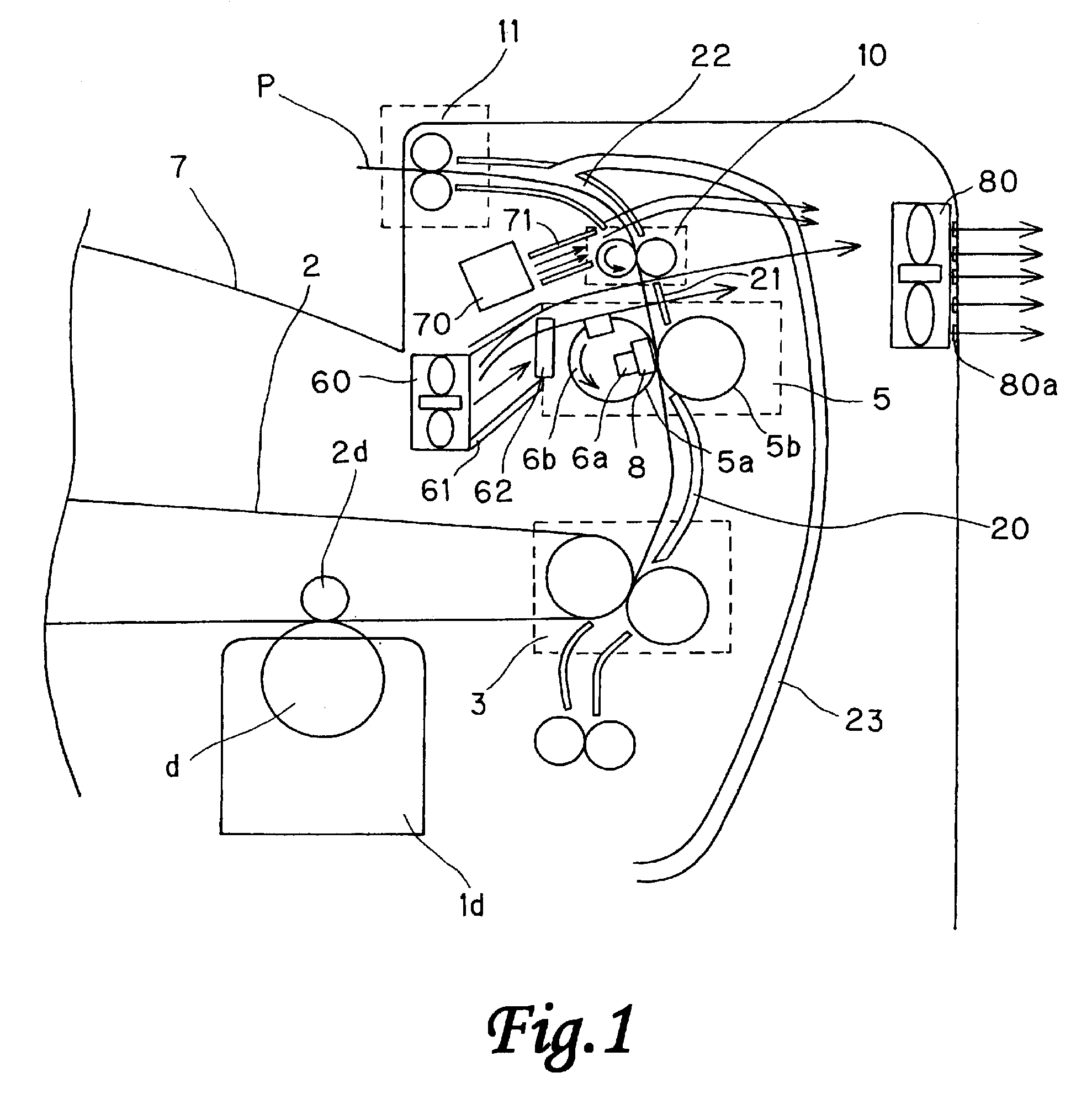
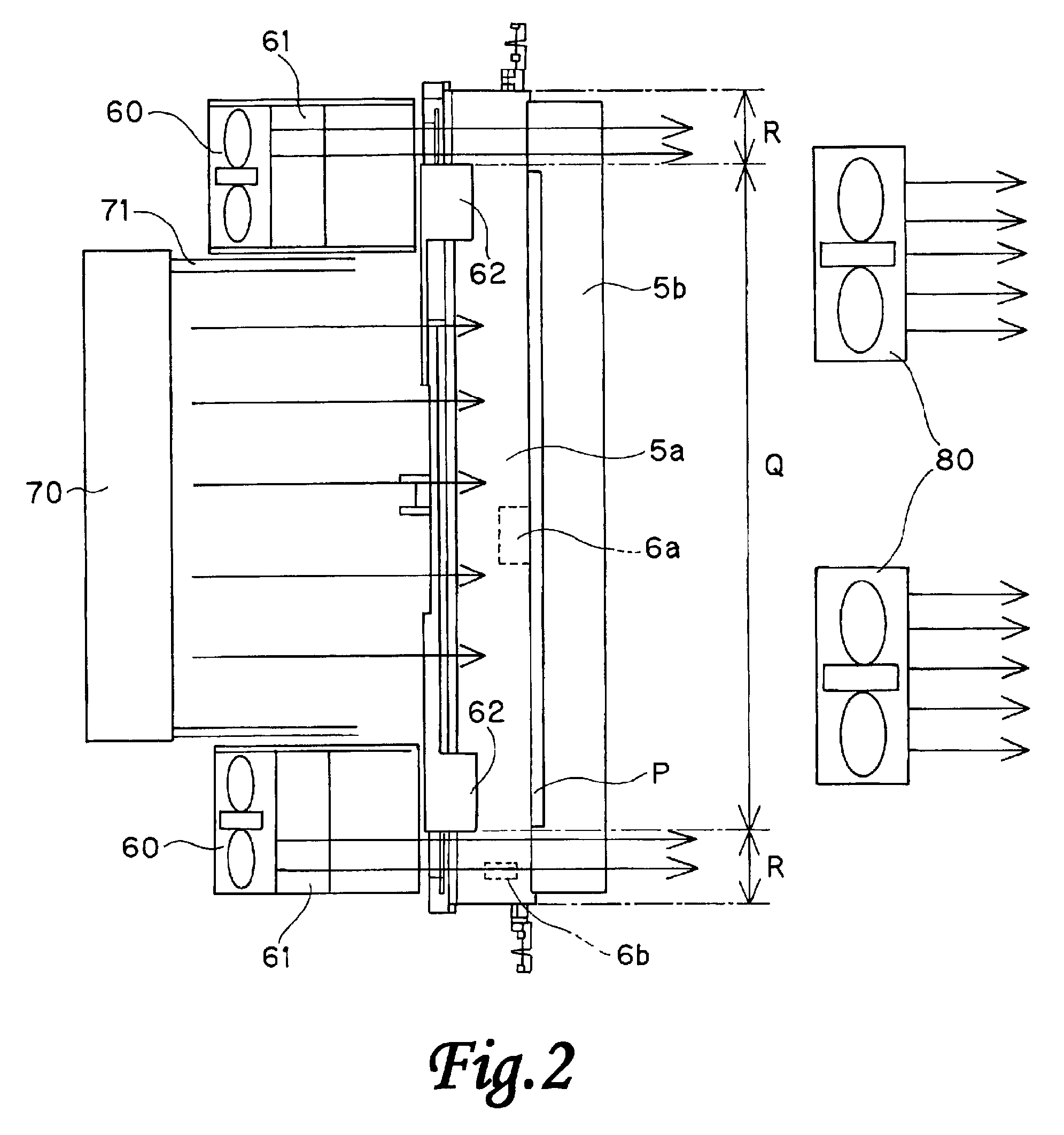
[0022]FIG. 1 shows an outline of a configuration of an image forming apparatus of the invention. FIG. 2 shows a configuration of an image forming apparatus in an embodiment of the invention. FIG. 3 is a sectional view of an image forming apparatus. ...


PUM


Abstract

An image forming apparatus includes a fixing member for fixing toner images on a sheet by heat, a first blowing device for blowing air for cooling the fixing member, and a second blowing device for blowing air for cooling the sheet on which toner images are fixed by the fixing member at the downstream side in conveying direction from the fixing member. The second blowing device blows air at a flow rate related to a flow rate at which the first blowing device blows air.

Description

BACKGROUND OF THE INVENTION [0001] 1. Field of the Invention [0002] The present invention relates to an image forming apparatus for forming an image on a sheet. [0003] 2. Description of the Related Art [0004] Recently, smaller size and higher speed have been demanded in an image forming apparatus. Such image forming apparatus is often accompanied by technical problems. That is, for example, heat is transferred to a recording material in the fixing means, so that the conveyed recording material becomes a heat source and the temperature of the entire apparatus is raised. [0005] As a second problem, in the recording material receiving heat, when sheets are discharged and stacked continuously, sheets are adhered to each other between the face and back side of the recording material. Sticking of sheets is likely to occur on OHT (Over Head Transparency) sheets or thick paper when the heating performance is improved in the fixing device or when sheets of thin paper printed on both sides ar...

Claims


Application Information

Patent Timeline
IPC IPC(8): G03G21/20G03G15/20
CPCG03G2215/00426G03G15/6573
Inventor KANAI, DAI
Owner CANON KK
Why Eureka
Try Eureka