

RF systems and methods for providing visual, tactile, and electronic indicators of an alarm condition
a technology of radio frequency identification and alarm condition, applied in the field of radio frequency (rf) systems and methods, can solve problems such as temperature history profile, material deterioration, and user's need for an interrogator to be presen
Active Publication Date: 2007-12-13
ZEST LABS INC
View PDF59 Cites 70 Cited by
- Summary
- Abstract
- Description
- Claims
- Application Information
AI Technical Summary
Benefits of technology
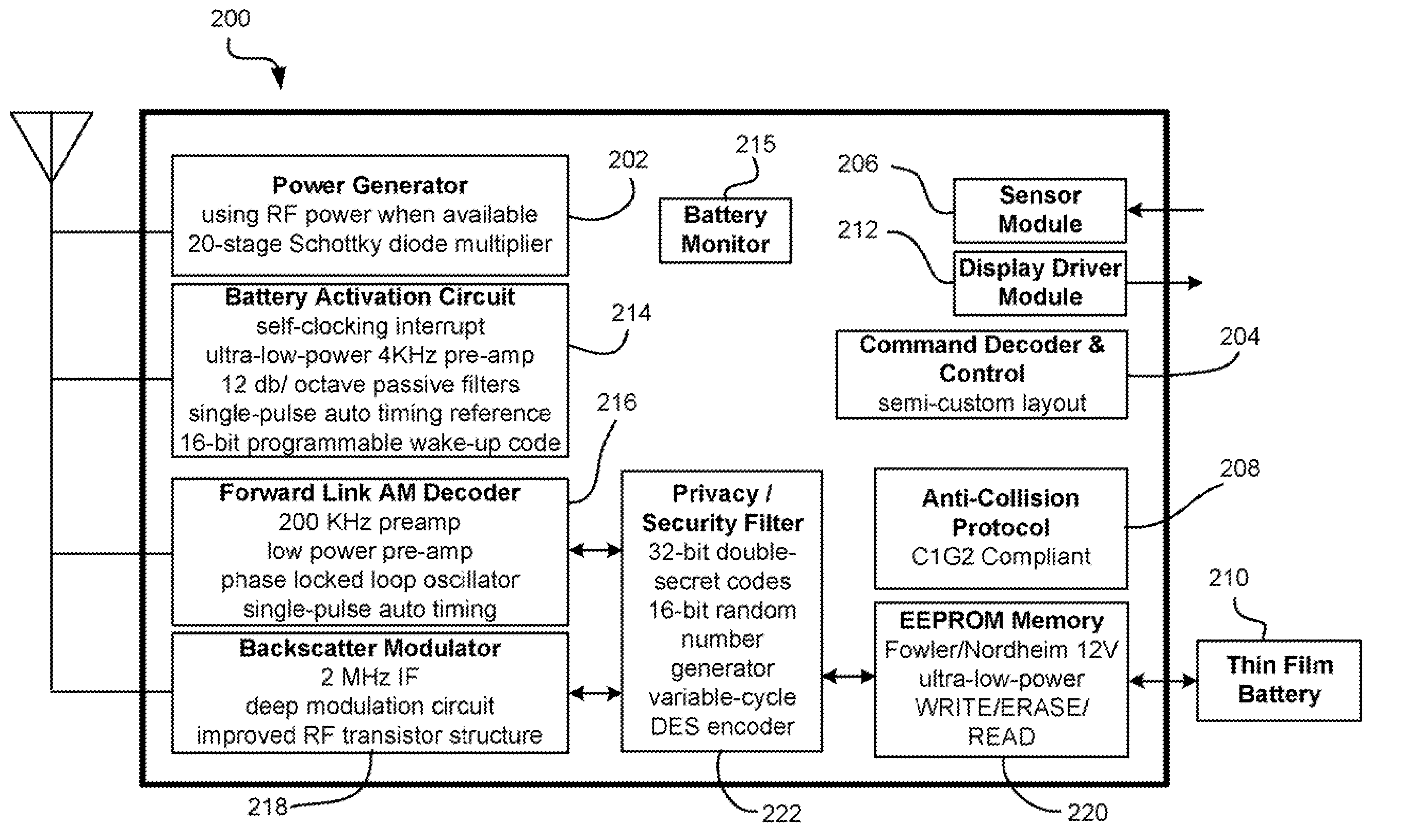
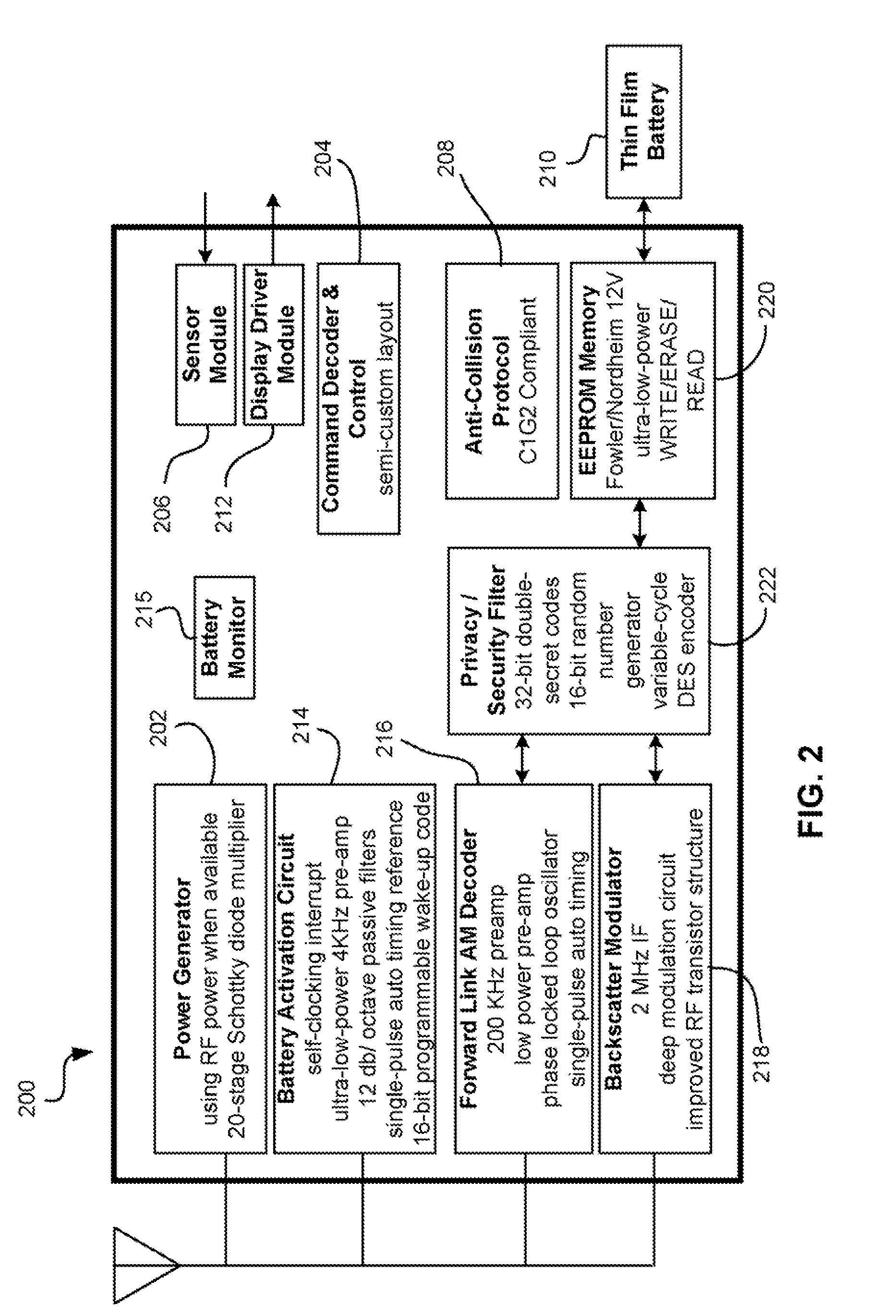
[0010]A Radio Frequency Identification (RFID) tag according to one embodiment includes a controller for setting one or more alarm state upon occurrence of one or more alarm conditions, and a visual display device or other alarm indicator (e.g., audible output device such as a buzzer or speaker outputting a beep, tact
Problems solved by technology
However, one major drawback of RFID when used in the supply chain to monitor, for example a temperature history profile of goods in transit, is that the user must have an interrogator present in order to read the temperature history profile.
That is, the materials have a tendency to deteriorate with time, and this tendency to deteriorate is often accelerated by exposure to higher temperatures.
By contrast, a material that deteriorates quickly in response to higher temperatures is said to have a “low stability”.
Excessive deterioration eventually results in the material in question being rendered unfit to use, or even rendered dangerous.
Since curing, incubation, or heat treatment processes are often temperature dependent, typically taking longer to proceed at lower temperatures, such materials must undergo a certain minimal time-temperature history before they are fit for use.
One drawback of such devices is that such devices may not be reusable.
This can be expensive.
Another drawback of such devices is that the devices are typically not accurate.
For example, known visual temperature indicators which are chemically mediated give immediate visual results, but are not particularly accurate.
The drawback of this chemical approach, however, is that most materials of interest, such as biological materials, often may have unique and complex time-temperature profiles.
By contrast, however, there are only a limited number of sensor chemicals that are suitable for visual time-temperature indicators.
It is often difficult or impossible to find an exact match, over all temperatures, between the degradation rate of the sensor chemical, and the degradation rate of the material of interest.
Although this scenario will insure that the user does not inadvertently accept degraded material, it is inefficient.
In many case, material that is, in fact, still good may be inappropriately discarded due to poor time-temperature indicator accuracy.
Of course, the alternative scenario, in which the chemical time-temperature indicator fails to adequately warn that the tracked material is degraded, is both unacceptable and potentially dangerous.
A further drawback of such devices is that they are prone to tampering.
However, the device is then not visually accessible until the package is opened.
Thus, a user may not be readily able to analyze the temperature profile unless he or she has an interrogator present.
Method used
View moreImage
Smart ImageViewing Examples

Examples
example
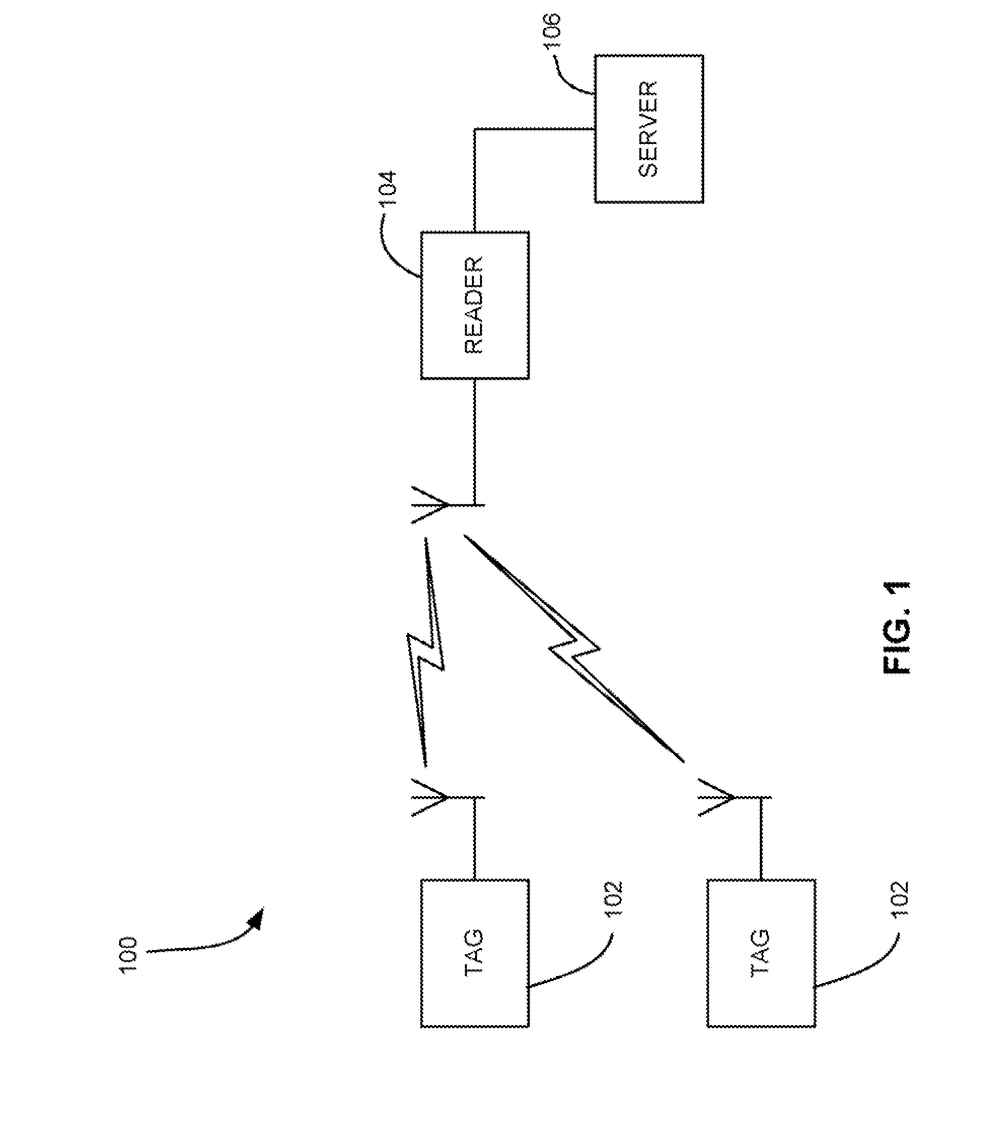
[0114]A master tag having a temperature sensor is placed on the outside of a pallet stacked with goods. Tags having temperature sensors are coupled to cases of items on the pallet. The master tag is programmed to set an alarm state if the ambient temperature exceeds a threshold. When temperature exceeds the threshold, the master tag alarm flag is set and an activate command is sent to the tags on the pallet. The tags wake up and begin monitoring a temperature profile of the object to which attached or its environment.
Login to View More PUM
 Abstract
A Radio Frequency Identification (RFID) tag according to one embodiment includes a controller for setting one or more alarm states upon occurrence of one or more alarm conditions, and a visual display device under control of the controller, the visual display device providing a visual, audible, and / or tactile indicator of an alarm condition when an alarm state is set. The visual, audible, and / or tactile indicator of the alarm condition optionally can only be reset by an authorized entity, or cannot be reset.
Description
FIELD OF THE INVENTION[0001]The present invention relates to Radio Frequency (RF) systems and methods, and more particularly, this invention relates to Radio Frequency Identification (RFID) systems and methods for providing visual and electronic indicators of an alarm condition.BACKGROUND OF THE INVENTION[0002]RFID systems are fast becoming the identification medium of choice due to the speed and accuracy with which a user can identify the quantity and type of tagged items present. RFID also holds promise as a medium for gathering information about tagged items and their environments, such as temperature history profiling. However, one major drawback of RFID when used in the supply chain to monitor, for example a temperature history profile of goods in transit, is that the user must have an interrogator present in order to read the temperature history profile. Consider the following.[0003]Many materials in use in commerce, medicine, and other areas are perishable. That is, the mater...
Claims
Login to View More Application Information
Patent Timeline
 IPC IPC(8): G08B1/08G08B13/14
CPCA61J1/14A61J2205/20G06K19/0707G06K19/0712G06K19/0717A61J2205/70G06K19/07749G08B13/2417G08B13/2457G08B25/008A61J2205/60G06K19/07703
InventorBATRA, NARESHSCHLICHT, LAUREN MARIE
OwnerZEST LABS INC