Projection type image display device

Active Publication Date: 2007-12-13
MAXELL HLDG LTD
View PDF2 Cites 18 Cited by
  • Summary
  • Abstract
  • Description
  • Claims
  • Application Information

AI Technical Summary

Benefits of technology

[0007]However, in the above projection optical system, the compact property is emphasized, and the aspherical mirror or the free-shaped surface mirror is employed in the outgoing optical part to remarkably reduce the projection distance. For that reason, since the angle of view is

Problems solved by technology

For that reason, since the angle of view is extremely large, the above technique has suffered from such a problem that an angle at which the image lights at both

Method used


Image

  • Projection type image display device
  • Projection type image display device
  • Projection type image display device

Examples


Embodiment Construction

[0020]Hereinafter, a description will be given of an embodiment of the present invention with reference to the accompanying drawings. The present invention is not limited to an example shown in the figure.

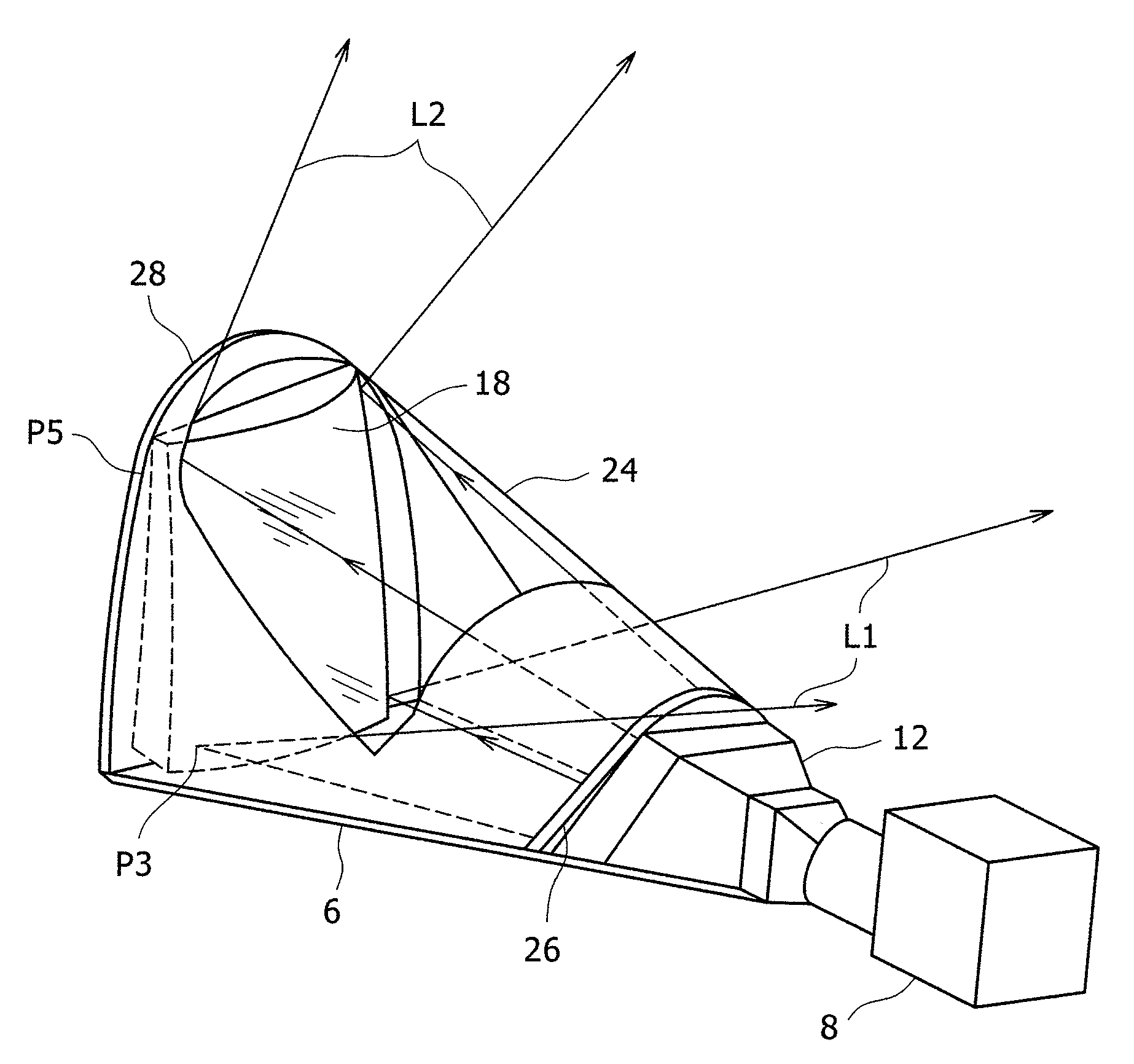
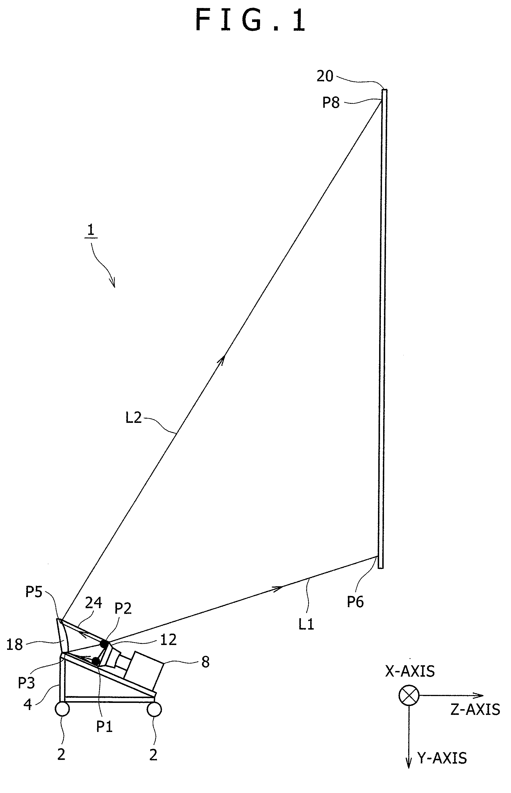
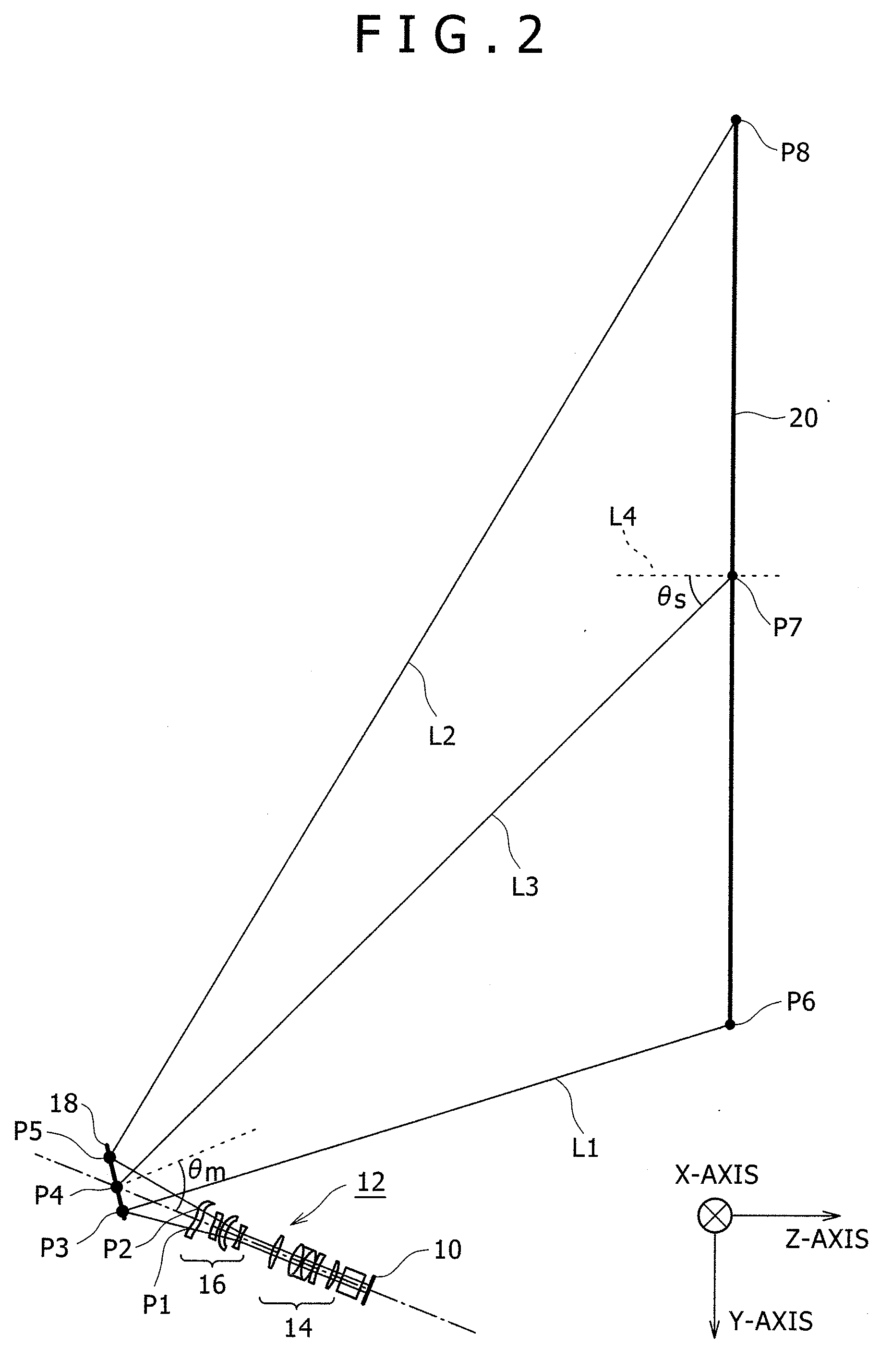
[0021]FIG. 1 is a cross-sectional view showing the outline of a projection type image display device 1 according to an embodiment of the present invention. FIG. 2 is a side view showing the main portion of an optical system in the projection type image display device.

[0022]FIGS. 1 and 2 show the main portion of the optical system with a Y-Z cross section in the X, Y, and Z orthogonal coordinate system. In this example, it is assumed that an origin of the X, Y, and Z orthogonal coordinate system is in the center of the display screen of an image display element 10 that forms an image generation source 8 that will be described later, and a Z-axis is in parallel to a normal to a screen 20 that will be described later. It is assumed that a Y-axis is in parallel with a direction along s...


PUM


Abstract

Both ends of a transparent cover which is formed of a curved member are fitted to a lens guard and a mirror guard, and a free-shaped surface mirror and a free-shaped surface lens are housed in a sealed space defined within a projection type image display device.

Description

CLAIM OF PRIORITY[0001]The present application claims priority from Japanese application serial no. JP 2006-159233, filed on Jun. 8, 2006, the content of which is hereby incorporated by reference into this application.BACKGROUND OF THE INVENTION[0002](1) Field of the Invention[0003]The present invention relates to a projection type image display device.[0004](2) Description of the Related Art[0005]In a projection type image display device that projects an image at a given angle (for example, from a lower side of a screen) with respect to an oblique projection, that is, a normal to a screen principal plane, an aspherical mirror or a free-shaped surface mirror is employed in an outgoing optical part of a projection optical system. In general, those mirrors are manufactured by molding with a resin and depositing aluminum or silver, taking mass productivity into consideration. However, the lenses are liable to be charged, and therefore liable to be contaminated with the dust or dirt in ...

Claims


Application Information

Patent Timeline
IPC IPC(8): G02B27/18
CPCG02B5/08G03B21/10H04N9/3141G03B21/28G03B21/14G03B21/147
Inventor IMAFUKU, DAISUKEHISADA, TAKANORIYOSHIKAWA, HIROKI
Owner MAXELL HLDG LTD
Why Eureka
Try Eureka