Display panel

Inactive Publication Date: 2007-12-13
SAMSUNG ELECTRONICS CO LTD
View PDF3 Cites 10 Cited by
  • Summary
  • Abstract
  • Description
  • Claims
  • Application Information

AI Technical Summary

Benefits of technology

[0036]In still another aspect of the present invention, there is provided a film attached to a display panel, which includes a plurality of light guides collecting and emitting light outputted from the display panel, a plurality of external light filtering members formed

Problems solved by technology

Although it has a high luminous efficiency, the facing discharge plasma display panel

Method used


Image

  • Display panel
  • Display panel
  • Display panel

Examples


Embodiment Construction

[0043]Certain embodiments of the present invention will now be described in greater detail with reference to the accompanying drawings.

[0044]In the following description, same drawing reference numerals are used for the same elements even in different drawings. The matters defined in the description such as a detailed construction and elements are provided to assist in a comprehensive understanding of the invention. Thus, it is apparent that the present invention can be carried out without those defined matters. Also, well-known functions or constructions are not described in detail since they would obscure the understanding of the invention.

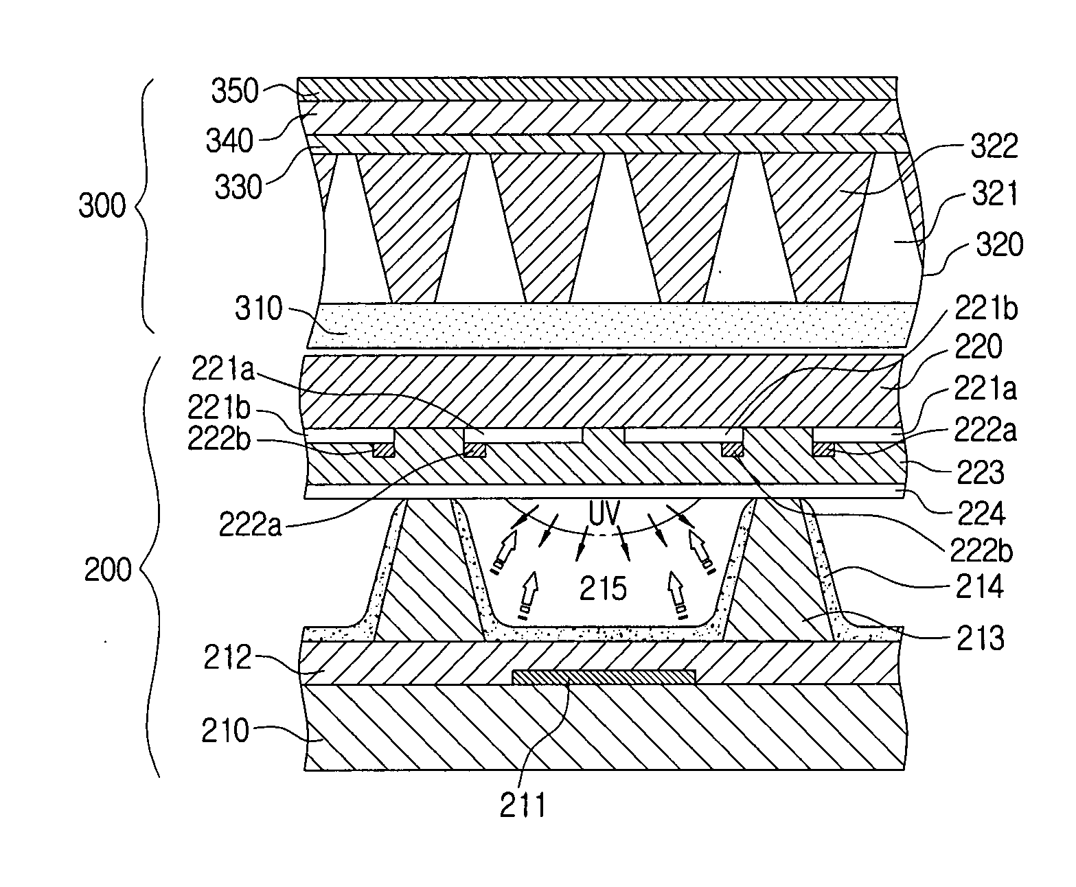
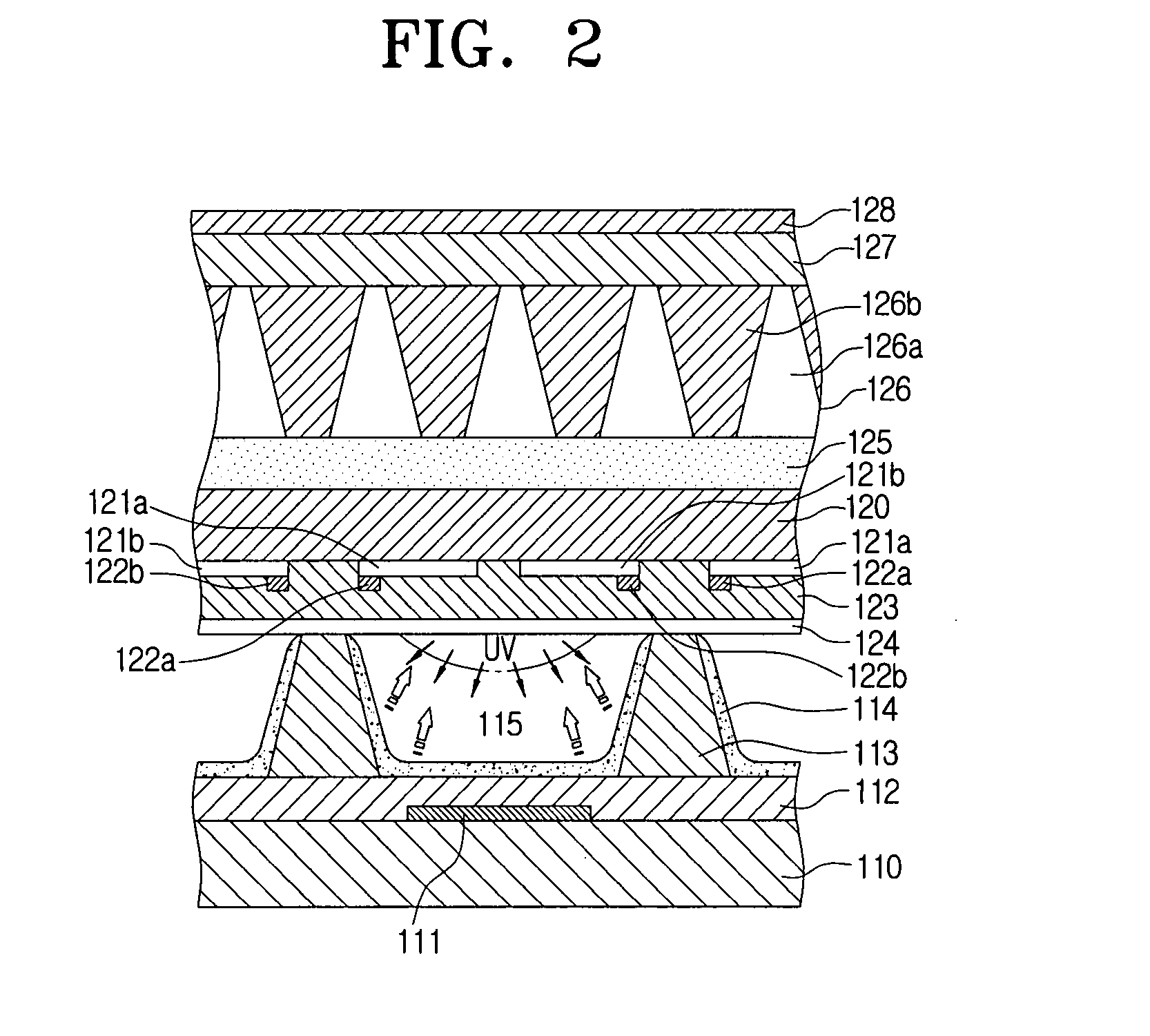
[0045]FIG. 2 is a view depicting the construction of a plasma display panel according to an embodiment of the present invention.

[0046]Referring to FIG. 2, the plasma display panel according to an embodiment of the present invention includes an upper substrate 120 and a lower substrate 110 which are spaced apart from each other. A plurality of di...


PUM


Abstract

A display panel is disclosed. The display panel includes an upper substrate through which light used for an image display passes and a plurality of light guides collecting and emitting the light transmitted through the upper substrate. The display panel may further include anti-reflective part, EMI shielding part, infrared filtering part or glass substrate to increase the bright room contrast or to improve the image displayed by the display panel.

Description

CROSS-REFERENCE TO RELATED APPLICATIONS[0001]This application claims the benefit under 35 U.S.C. §119 of Korean Patent Application No. 10-2006-051010, filed Jun. 7, 2006, in the Korean Intellectual Property Office, the entire disclosure of which is incorporated herein by reference.BACKGROUND OF THE INVENTION[0002]1. Field of the Invention[0003]The present invention relates to a display panel, and more particularly, to a plasma display panel having an improved structure displaying an image.[0004]2. Description of the Related Art[0005]In general, a plasma display panel (PDP) is a device that displays an image using electric discharge. Such a plasma display panel has become very popular since the plasma display panel has a superior display performance in luminance and viewing angle.[0006]The plasma display panel is classified into a facing discharge type and a surface discharge type depending on the arrangement of electrodes. In the facing discharge plasma display panel, a pair of sust...

Claims


Application Information

Patent Timeline
IPC IPC(8): G02B5/22H01J11/12H01J11/44
CPCH01J11/12H01J2211/444H01J2211/442H01J11/44G02B5/20
Inventor YOON, SEOK-ILNHO, JEONG-HOLIM, SUNG-HWANJEON, WOOK-JAELEE, DAE-HEE
Owner SAMSUNG ELECTRONICS CO LTD
Why Eureka
Try Eureka