Precise linear fastener system and method for use

a linear fastener and precise technology, applied in the field of fasteners, can solve the problems of limiting the device to light-duty applications, limiting the device to the amount of torque which can be applied to the threaded segments, and adding to the complexity of the device, so as to achieve precise tensile loads, precise linear engagement and disengagement, and precise connection.

Inactive Publication Date: 2007-12-13
ORTHO INNOVATIONS +1
View PDF31 Cites 28 Cited by
  • Summary
  • Abstract
  • Description
  • Claims
  • Application Information

AI Technical Summary

Benefits of technology

[0015] The present invention provides a linear fastening system capable of rapid linear engagement and disengagement. More specifically, the system utilizes a interlocking collet member and a compression ring member which are constructed and arranged to slip easily over a shank member while in a first release position. The collet member is constructed and arranged with an inner engaging surface and an outer ribbed compression surface, the compression ring member being constructed and arranged with an inner ribbed compression surface preferably conjugate in shape with respect to the outer surface of the collet member. The fastener system is secured by sliding the compression member in a linear overlapping fashion over the collet member, thereby utilizing the ribbed surfaces to compress the collet member and place a tensile load on the compression ring to grip the outer surface of the shank member. In this manner, the linear fastener system is capable of providing a precise, secure, and reproducible connection between multiple components without the need to apply rotational torque to the assembly. The connection also allows full thread engagement and a locking connection without the need for plastic inserts or adhesives. When compared to traditional threaded fasteners, the dual ribbed compression surfaces allow very precise tensile loads to be applied to the shank member. Prior art designs require torque wrenches to apply measured clamping loads to fasteners. Linear compression of the collet member eliminates variations as seen in the prior art due to surface finish, lubrication and thread engagement to achieve a precise clamping load.
[0016] Accordingly, it is an objective of the present invention to provide a fastener system capable of precisely and reproducibly securing multiple components into a single assembly without the need to apply-torque to the assembly.
[0017] An additional objective of the present invention is to provide a fastener system capable of precise and reproducible linear engagement and disengagement.
[0018] It is a further objective of the present invention to provide a fastener system capable of providing precise and reproducible linear engagement to externally threaded surfaces and the like.
[0019] A still further objective of the present invention is to provide a fastener system capable of providing precise and reproducible linear engagement to snap ring grooves and the like.
[0022] Still yet another objective of the present invention is to provide a fastener system that allows close spacing and does not require wrench clearances.

Problems solved by technology

In addition, ball assemblies are required to maintain proper alignment and locking action of the threaded segments, further adding to the complexity of the device.
In addition, the amount of torque which can be applied to the threaded segments is limited to that which the pins and the oval indentations can withstand, limiting the device to light duty applications.
As the device is tightened the threaded segments increase pressure against the fastener making the task of torquing the fastener to a specified torque difficult.
In addition, due to the size of the device, it requires additional space for wrench clearance and the like.
While the prior art devices allow partials linear engagement they require rotational torque to produce the clamping forces required to maintain assemblies.
These devices also require extensive machining of thin sections and require difficult assembly processes for manufacture.
This combination results in high production cost and weak finished components.
The designs of the prior art devices do not lend themselves to traditional fastener manufacturing techniques, e.g. cold forming, thread rollers, pointers, nut tappers, slotters, shavers etc., adding to the high manufacturing cost and reducing the strength of the fasteners.

Method used


Image

  • Precise linear fastener system and method for use
  • Precise linear fastener system and method for use
  • Precise linear fastener system and method for use

Examples


Embodiment Construction

[0046] Although the invention is described in terms of a preferred specific embodiment, it will be readily apparent to those skilled in this art that various modifications, rearrangements and substitutions can be made without departing from the spirit of the invention. The scope of the invention is defined by the claims appended hereto.

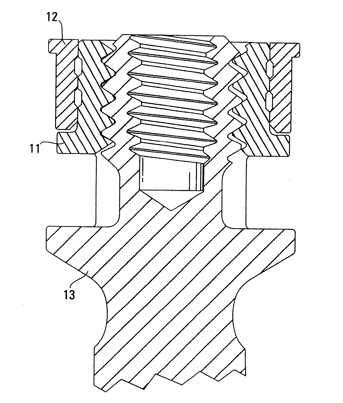
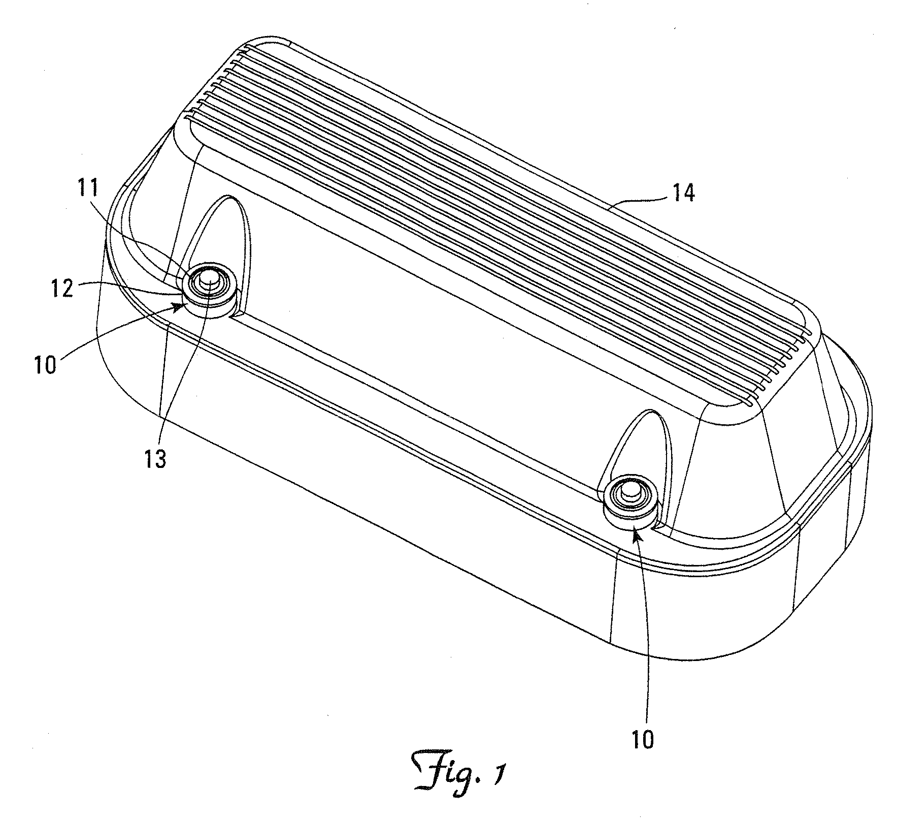
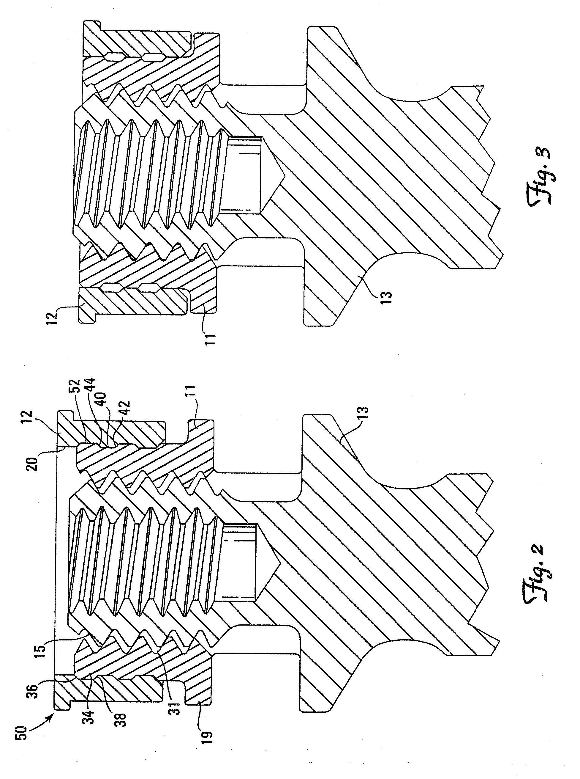
[0047] The linear engaging fasteners 10 utilized to secure the automotive valve cover 14, shown in FIG. 1, are a representation of the general utility of the present invention. Referring to FIGS. 2 and 3, the linear fastener generally includes an axially aligned collet member 11 and a compression ring member 12 which are constructed and arranged to cooperate with a shank member 13. The external surface 18 of collet member 11 is constructed generally cylindrical with at least one and preferably three outwardly and circumferentially extending rib(s) 34 positioned about a central axis. Each rib 34 being constructed with a first ramp surface 36 to allow ...


PUM


Abstract

The present invention provides a linear fastening system capable of rapid engagement and disengagement. More specifically, the system utilizes a cooperating collet member and a compression ring member which are constructed and arranged to slip easily over a shank member. The fastener system is secured by linearly traversing a compression member in an overlapping fashion over the collet member thereby utilizing ribbed surfaces to compress the collet member to grip the outer surface of the shank member. In this manner, the linear fastener system is capable of providing a precise, secure, and reproducible connection between multiple components without the need to apply rotational torque to the assembly.

Description

REFERENCE TO RELATED APPLICATIONS [0001] This application is a continuation of U.S. patent application Ser. No. 10 / 618,689, filed Jul. 9, 2003 (pending), the disclosure of which is incorporated herein by reference in its entirety. This application is related to U.S. patent application Ser. No. 10 / 358,427, filed Apr. 3, 2003 (now U.S. Pat. No. 7,105,029), the disclosure of which is incorporated herein by reference in its entirety.FIELD OF THE INVENTION [0002] The present invention relates to fasteners capable of rapid linear engagement and disengagement. More specifically, the system utilizes a combination of interlocking sleeve members which combine to form a versatile and effective fastener system which may be used to connect components together without placing torque on the assembly. BACKGROUND OF THE INVENTION [0003] In general, a fastener is any device used to connect or join two or more components to create an assembly. In the field of manufacturing there are numerous assembly ...

Claims


Application Information

Patent Timeline
Patent Type & Authority Applications(United States)
IPC IPC(8): F16B37/08F16B21/16F16B21/18
CPCF16B21/16F16B37/0864F16B21/186
Inventor DOUBLER, ROBERT L.HAMMILL, JOHN E. SR.
Owner ORTHO INNOVATIONS
Why Eureka
Try Eureka