Linear fastener system and method for use

a technology of linear fasteners and threaded segments, which is applied in the field of linear fasteners, can solve the problems of limiting the device to light-duty applications, the complexity of the device, and the limited torque which can be applied to the threaded segments, so as to achieve precise tensile loads, precise clamping loads, and linear linear engagement and disengagement.

Active Publication Date: 2005-03-10
SPINAL
View PDF41 Cites 36 Cited by
  • Summary
  • Abstract
  • Description
  • Claims
  • Application Information

AI Technical Summary

Benefits of technology

[0015] The present invention provides a linear fastening system capable of rapid linear engagement and disengagement. More specifically, the system utilizes a cooperating collet member and a compression ring member which are constructed and arranged to slip easily over a shank member while in a first release position. The collet member is constructed and arranged with an inner engaging surface and an outer tapered compression surface, the compression ring member being constructed and arranged with an inner tapered compression surface preferably conjugate in shape the outer surface of the collet member. The fastener system is secured by sliding the compression member in a linear overlapping fashion over the collet member, thereby utilizing the conical surfaces to compress the collet member and place a tensi

Problems solved by technology

In addition, ball assemblies are required to maintain proper alignment and locking action of the threaded segments, further adding to the complexity of the device.
In addition, the amount of torque which can be applied to the threaded segments is limited to that which the pins and the oval indentations can withstand, limiting the device to light duty applications.
As the device is tightened the threaded segments increase pressure against the fastener making the task of torquing the fastener to a specified torque difficult.
In addition, due to the size of the device, it requires additional space for wrench clearance and the l

Method used


Image

  • Linear fastener system and method for use
  • Linear fastener system and method for use
  • Linear fastener system and method for use

Examples


Embodiment Construction

[0044] Although the invention is described in terms of a preferred specific embodiment, it will be readily apparent to those skilled in this art that various modifications, rearrangements and substitutions can be made without departing from the spirit of the invention. The scope of the invention is defined by the claims appended hereto.

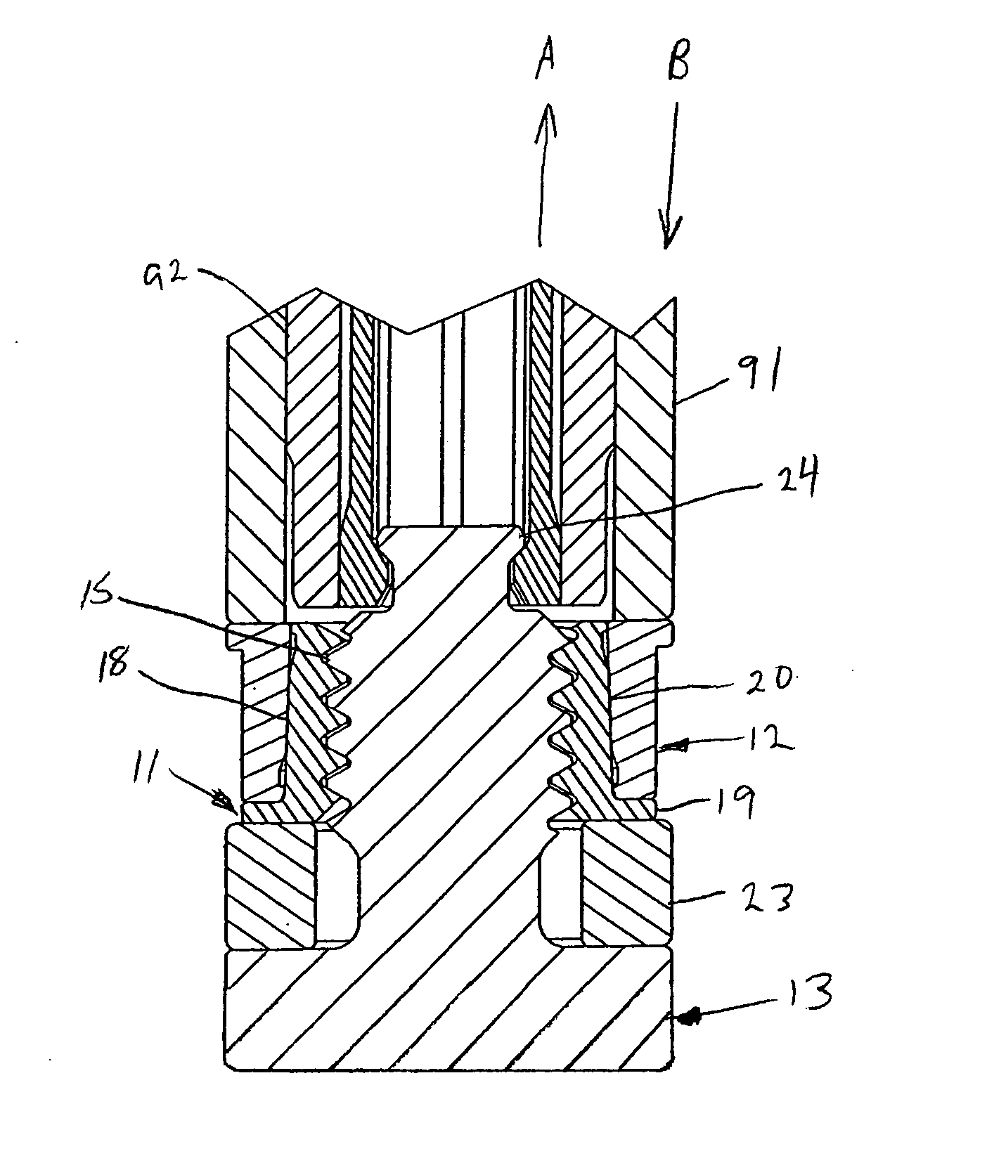
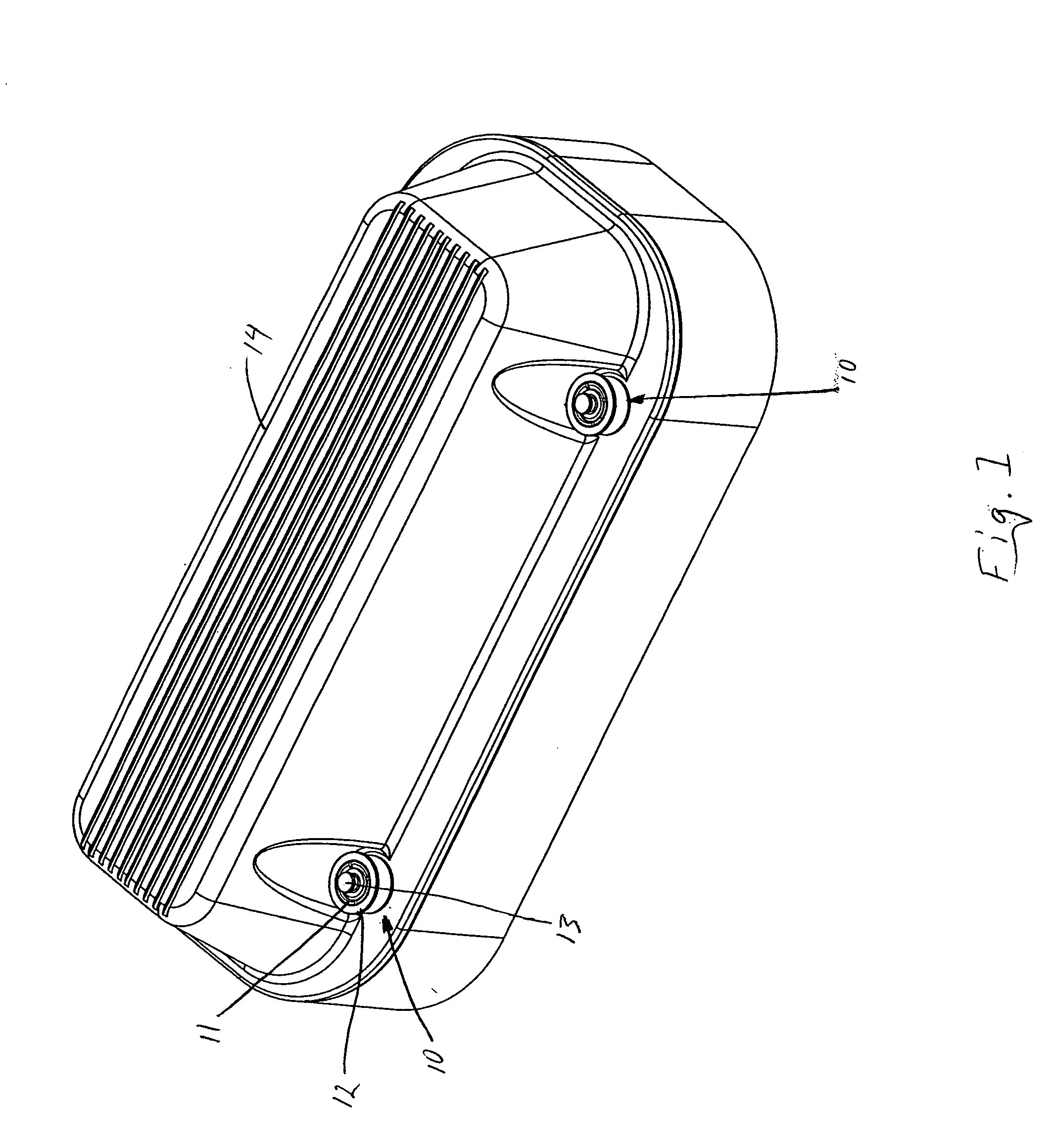
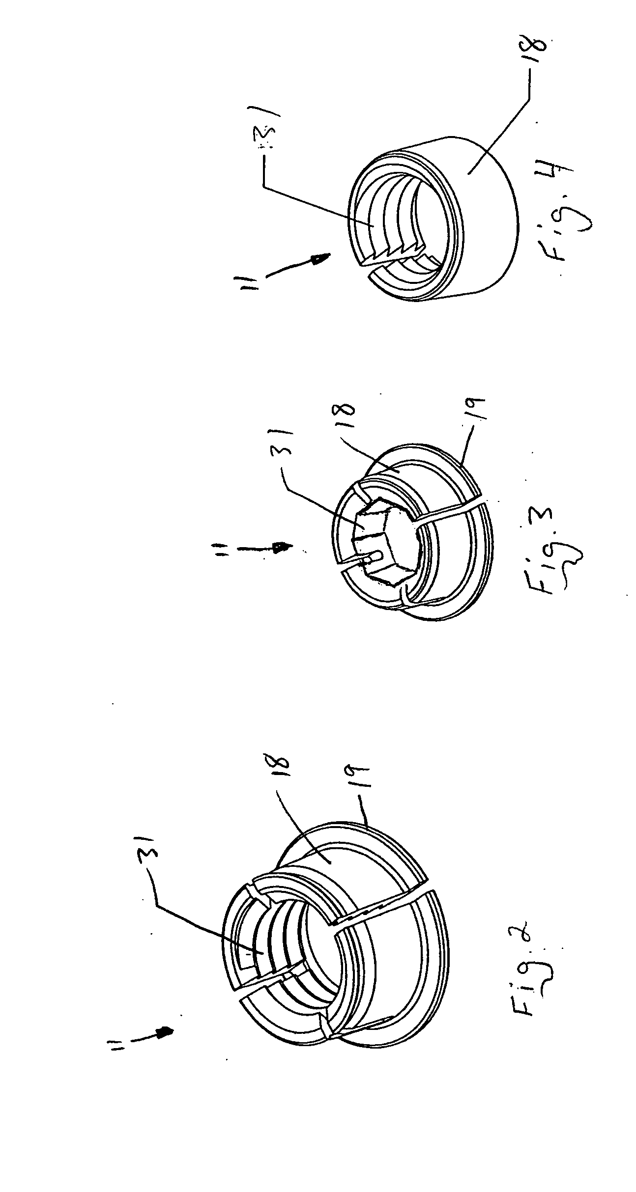
[0045] The linear engaging fasteners 10 utilized to secure the automotive valve cover 14, shown in FIG. 1, are a representation of the general utility of the present invention. The linear fastener generally includes a collet member 11 and a compression ring member 12 which are constructed and arranged to cooperate with a shank member 13. The collet member 11 shown in FIGS. 2 through 4, is slid or loosely threaded over the external gripping surface 15 of a shank member 13 generally shown in FIGS. 8 through 10. The external surface 18 of collet member 11 is tapered or conical in form. The internal gripping surface 31 of collet member 11 is generally co...


PUM


Abstract

The present invention provides a linear fastening system capable of rapid engagement and disengagement. More specifically, the system utilizes a cooperating collet member and a compression ring member which are constructed and arranged to slip easily over a shank member. The fastener system is secured by sliding a compression member in a linear overlapping fashion over the collet member thereby utilizing the conical surfaces to compress the collet member to grip the outer surface of the shank member. In this manner, the linear fastener system is capable of providing a secure connection between multiple components without the need to apply rotational torque to the assembly.

Description

REFERENCE TO RELATED APPLICATIONS [0001] This application is related to patent application Ser. No. 10 / 358,427, filed Apr. 4, 2003, the contents of which are herein incorporated by reference in their entirety.FIELD OF THE INVENTION [0002] The present invention relates to fasteners capable of rapid linear engagement and disengagement. More specifically, the system utilizes a combination of interlocking sleeve members which combine to form a versatile and effective fastener system which may be used to connect components together without placing torque on the assembly. BACKGROUND OF THE INVENTION [0003] In general, a fastener is any device used to connect or join two or more components to create an assembly. In the field of manufacturing there are numerous assembly processes requiring individual components to be joined with fasteners to create an assembled product. Most of these processes, requiring fixations of one component in relation to another are currently performed using threade...

Claims


Application Information

Patent Timeline
IPC IPC(8): F16B37/08
CPCY10T403/7067F16B37/0864
Inventor DOUBLER, ROBERT L.HAMMILL, JOHN E. SR.
Owner SPINAL
Why Eureka
Try Eureka