Orthodontic indirect bonding tray with moisture control

a technology of indirect bonding and moisture control, which is applied in the field of indirect bonding apparatus of orthodontics, can solve the problems that the control of moisture during indirect bonding procedures is often considered more difficult, and achieve the effect of reducing the probability of a compromised adhesive bond and subsequent inadvertent detachment of the appliance during the course of treatment due to bond failure, and reducing the passage of moistur

Active Publication Date: 2007-12-13
3M INNOVATIVE PROPERTIES CO
View PDF11 Cites 19 Cited by
  • Summary
  • Abstract
  • Description
  • Claims
  • Application Information

AI Technical Summary

Benefits of technology

[0012]The present invention relates to improved indirect bonding apparatus that has structure for controlling moisture such as saliva during a bonding procedure. In particular, the present invention concerns an indirect bonding apparatus that includes a tray having structure that functions as a moat to help confine or at least hinder the passage of moisture in directions toward the orthodontic bonding adhesive while the adhesive is curing. As a result, the probability of a compromised adhesive bond and subsequent inadvertent detachment of the appliances during the course of treatment due to bond failure is reduced.
[0019]maintaining a space between the wall sections and the patient's teeth in a region next to the base of the appliances during at least a portion of the time that the adhesive contacts the patient's teeth in order to hinder the movement of moisture in a direction toward the adhesive.

Problems solved by technology

The control of moisture during a bonding procedure is often deemed important, since the presence of moisture can adversely affect the resultant bond strength between the appliance and the tooth.
The control of moisture during an indirect bonding procedure is often considered more challenging than controlling moisture during a direct bonding procedure.
In addition, many indirect bonding trays have interior wall sections that closely fit the patient's teeth, and consequently tend to spread moisture over relatively large portions of the tooth surface as the tray is placed onto the dental arch.

Method used


Image

  • Orthodontic indirect bonding tray with moisture control
  • Orthodontic indirect bonding tray with moisture control
  • Orthodontic indirect bonding tray with moisture control

Examples


Embodiment Construction

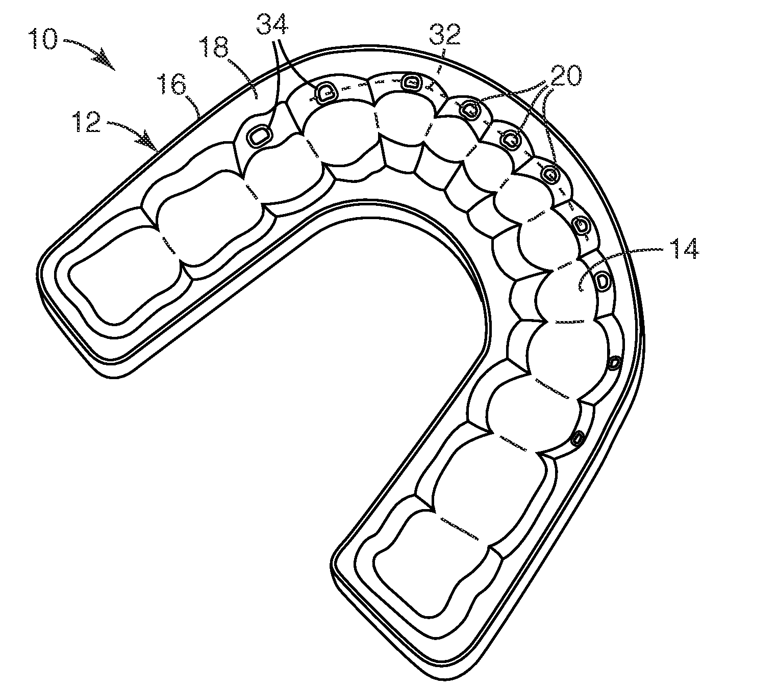
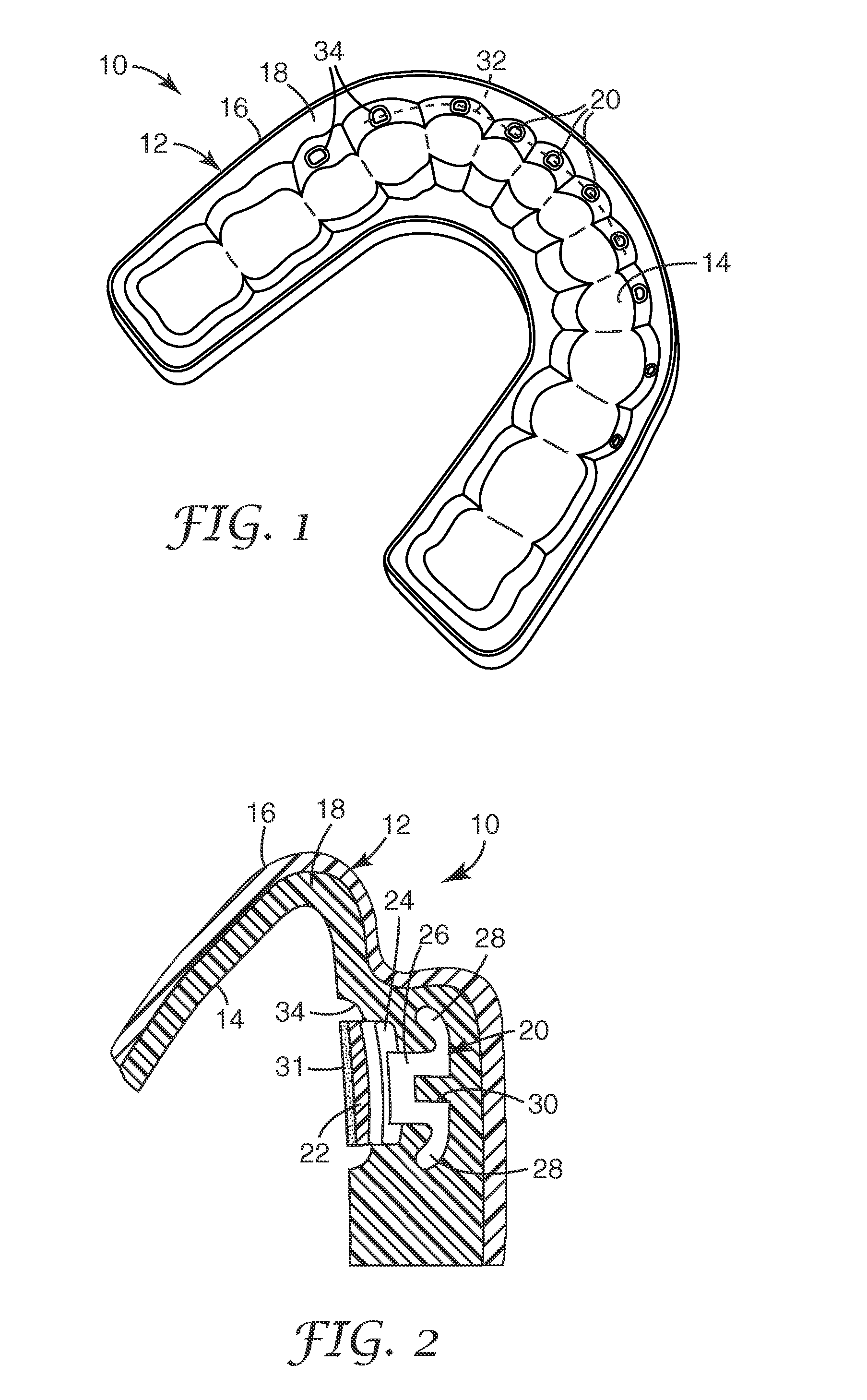
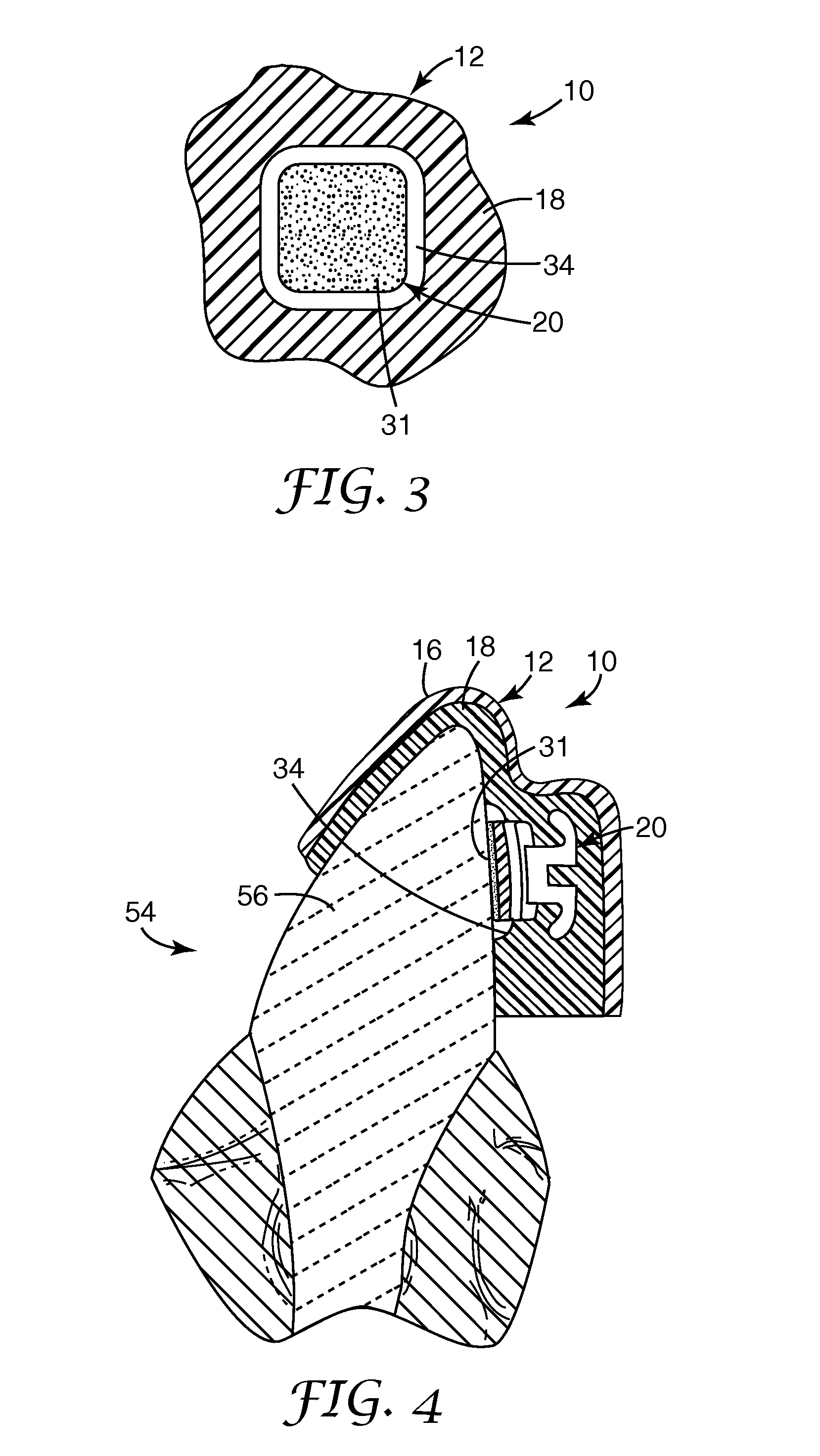
[0031]An apparatus for indirect bonding of orthodontic appliances according to one embodiment of the invention is illustrated in FIGS. 1-4 and is broadly designated by the numeral 10. The apparatus 10 includes a tray 12 having a channel 14 for receiving a patient's dental arch. In the exemplary tray 12 shown in the drawings, the channel 14 is adapted to receive a patient's lower dental arch, although it should be understood in this regard that as an alternative the tray 12 may be constructed to receive the patient's upper dental arch.

[0032]The tray 12 may be constructed according to any one of a variety of known techniques. In the example shown in FIGS. 1-4, the tray 12 includes an outer shell 16 that is relatively stiff and an inner section of matrix material 18 that is relatively flexible. A suitable material for the shell 16 is a sheet of polycarbonate such as Makrolon brand material from Bayer or Lexan brand polycarbonate from GE having a thickness of 0.06 in. (1.5 mm). Other ma...


PUM


Abstract

An indirect bonding apparatus for orthodontic bonding procedures includes a tray having inner wall sections defining a channel for receiving the patient's dental arch. A number of orthodontic appliances are detachably connected to the tray along the channel, and each appliance includes a base for bonding the appliance to the tooth. The wall sections include at least one groove extending along the base of at least one appliance in order to provide a space between the wall sections and the patient's tooth structure when the tray is received on the patient's dental arch. The space hinders the flow of oral fluids such as saliva in directions toward the base in order to help ensure that the fluids do not adversely affect the strength of the resulting adhesive bond between the appliance and the tooth.

Description

BACKGROUND OF THE INVENTION [0001]1. Field of the Invention[0002]This invention broadly relates to orthodontic indirect bonding apparatus that is useful for affixing orthodontic appliances to a patient's teeth. More particularly, the present invention is directed towards orthodontic indirect bonding apparatus with structure for controlling moisture in the oral cavity such as saliva during a bonding procedure.[0003]2. Description of the Related Art[0004]Orthodontic treatment involves movement of malpositioned teeth to desired locations in the oral cavity. Orthodontic treatment can improve the patient's facial appearance, especially in instances where the teeth are noticeably crooked or where the jaws are out of alignment with each other. Orthodontic treatment can also enhance the function of the teeth by providing better occlusion during mastication.[0005]One common type of orthodontic treatment involves the use of tiny, slotted appliances known as brackets. The brackets are fixed to...

Claims


Application Information

Patent Timeline
Patent Type & Authority Applications(United States)
IPC IPC(8): A61C3/00
CPCA61C7/146B33Y80/00
Inventor CINADER, DAVID K.CLEARY, JAMES D.KALGUTKAR, RAJDEEP S.
Owner 3M INNOVATIVE PROPERTIES CO
Why Eureka
Try Eureka