Air handler unit fan installation and control method

a technology for air handler units and fans, applied in mechanical equipment, refrigeration components, light and heating equipment, etc., can solve the problems of excessive electrical energy consumption, excessive cycling of system components, and inability to efficiently control the fan to match the load of the hvac system

Inactive Publication Date: 2007-12-20
EMERSON CLIMATE TECH RETAIL SOLUTIONS +1
View PDF23 Cites 96 Cited by
  • Summary
  • Abstract
  • Description
  • Claims
  • Application Information

AI Technical Summary

Problems solved by technology

Because such fans may only operate at either one or two fixed speeds, the fans may not be efficiently controlled to match HVAC system load.
Consequently, use of such fans may result in excessive electrical energy consumption, excessive cycling of system components, and excessive system component wear.
In a cooling mode, when the air handler fans

Method used


Image

  • Air handler unit fan installation and control method
  • Air handler unit fan installation and control method
  • Air handler unit fan installation and control method

Examples


Embodiment Construction

[0019] The following description is merely exemplary in nature and is not intended to limit the present disclosure, application, or uses. It should be understood that throughout the drawings, corresponding reference numerals indicate like or corresponding parts and features.

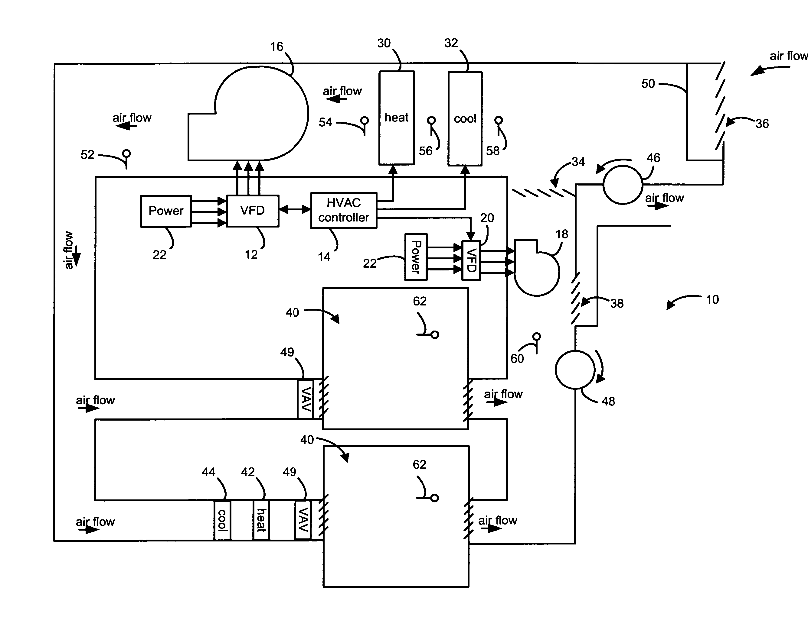
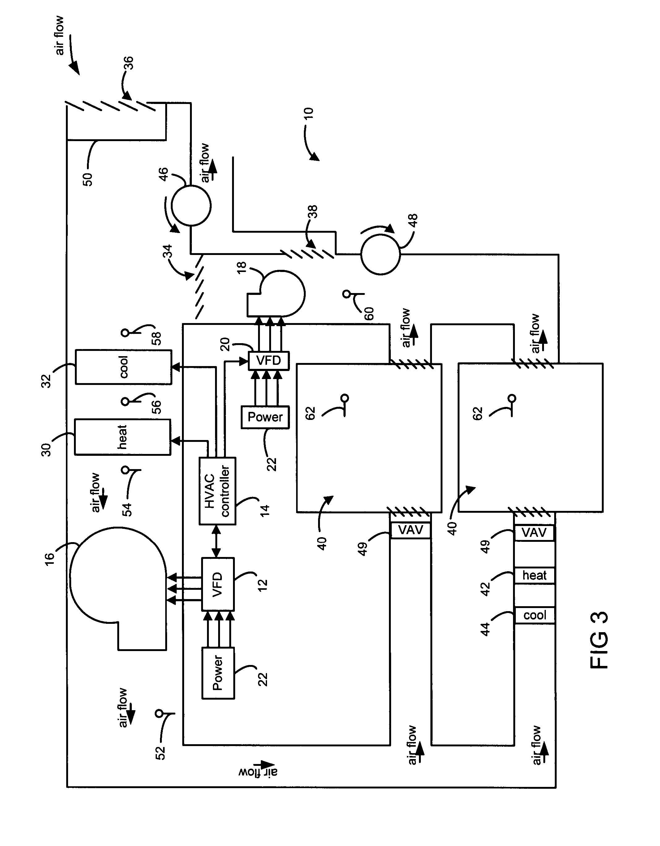
[0020] A method for installing a variable frequency drive (VFD) unit in an air handler unit of an HVAC system may include installing a VFD in line with a power supply to an air handler unit fan. In this way, a previously single or two speed fan may be converted to operate as a variable speed fan to allow for more efficient fan operation. By monitoring and comparing system conditions after VFD installation, a VFD control strategy may be implemented and adjusted to minimize a probability of a refrigerant flood-back condition, in a cooling mode, or an overheating condition, in a heating mode, while maximizing energy efficiency.

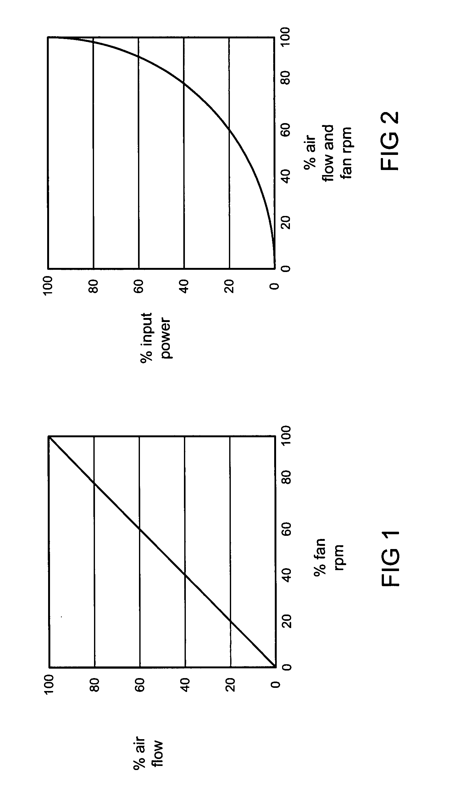
[0021] As shown in FIG. 1, fan air flow varies linearly with rotational fan speed. As sh...


PUM


Abstract

A method is provided including installing a variable frequency drive unit to drive a previously non-variable air handler fan of an HVAC system. The method includes setting a control strategy for the variable frequency drive. The control strategy includes a drive speed for each mode of the HVAC system. The method includes operating the HVAC system in each mode and monitoring the HVAC system. The method includes adjusting the HVAC system or the control strategy of the variable frequency drive to increase drive speed based on monitoring the HVAC system.

Description

CROSS-REFERENCE TO RELATED APPLICATIONS [0001] This application claims the benefit of U.S. Provisional Application No. 60 / 796,347, filed on Apr. 28, 2006, the disclosure of which is incorporated herein by reference.FIELD [0002] The present disclosure relates to an air handler unit fan installation and control method. BACKGROUND [0003] The statements in this section merely provide background information related to the present disclosure and may not constitute prior art. [0004] Heating, ventilating and air conditioning (HVAC) systems may generally be equipped with an air handler unit that may control the flow of air. Air handler units may traditionally be non-variable, in that the unit is equipped with a single or two speed fan that may operate at certain fixed or incremental speeds. Because such fans may only operate at either one or two fixed speeds, the fans may not be efficiently controlled to match HVAC system load. Consequently, use of such fans may result in excessive electrica...

Claims


Application Information

Patent Timeline
IPC IPC(8): F25B41/04
CPCF24F11/0079Y02B30/746F24F2011/0083F24F11/77F24F11/85Y02B30/70
Inventor MATHEWS, THOMAS J.
Owner EMERSON CLIMATE TECH RETAIL SOLUTIONS
Why Eureka
Try Eureka