Arrangement and method for automatically determined time constant for a control device

a control device and time constant technology, applied in refrigeration machines, process and machine control, refrigeration components, etc., can solve the problems of requiring technical expertise, requiring relatively time-consuming, and requiring bump tests

Active Publication Date: 2007-08-09
GENERAL CYBERNATION GRP INC DBA CYBOSOFT
View PDF8 Cites 30 Cited by
  • Summary
  • Abstract
  • Description
  • Claims
  • Application Information

AI Technical Summary

Benefits of technology

[0012] At least some embodiments of the invention address the above-described needs, as well as others, by providing a method of automatically calculating a time constant for an air handling unit subsystem, and or an arrangement that automatically calculates and uses a time constant in connection with an air handling unit control system.
[0013] A first embodiment of the system is an arrangement that includes a controller and a processing circuit. The controller is configured to control a device within an air handler unit, which includes at least a first coil. The processing circuit is configured to receive first information representative of a maximum liquid flow rate through the first coil and second information representative of a maximum air flow rate of the first coil. The processing circuit is further configured to generate a time constant estimate, based on the first information and second information. The time constant is used in the controller in performing control of the device.
[0014] The above described features and advantages, as well as others, will become more readily apparent to those of ordinary skill in the art by reference to the following detailed description and accompanying drawings.

Problems solved by technology

Bump tests have a disadvantage in that they are relatively time consuming, are labor intensive, and require technical expertise.
Thus, costly tests and expertise are needed on a job-site to program parameters into a control system that involves an air-handling unit.

Method used


Image

  • Arrangement and method for automatically determined time constant for a control device
  • Arrangement and method for automatically determined time constant for a control device
  • Arrangement and method for automatically determined time constant for a control device

Examples


example 1

Cooling Coil Process

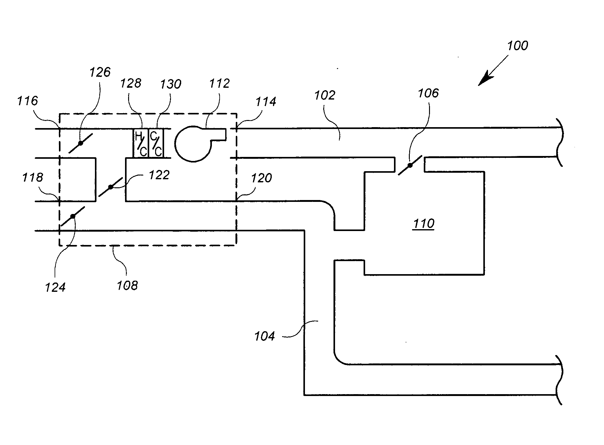
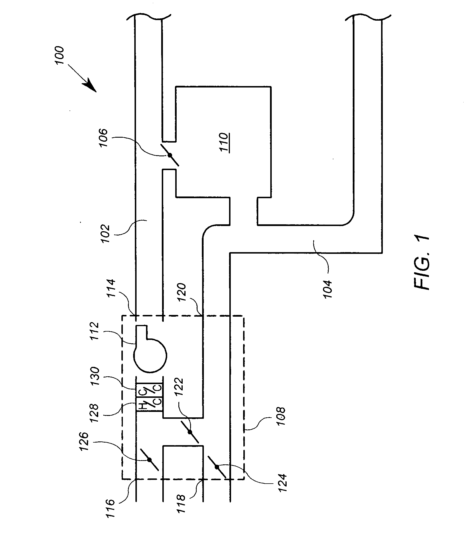
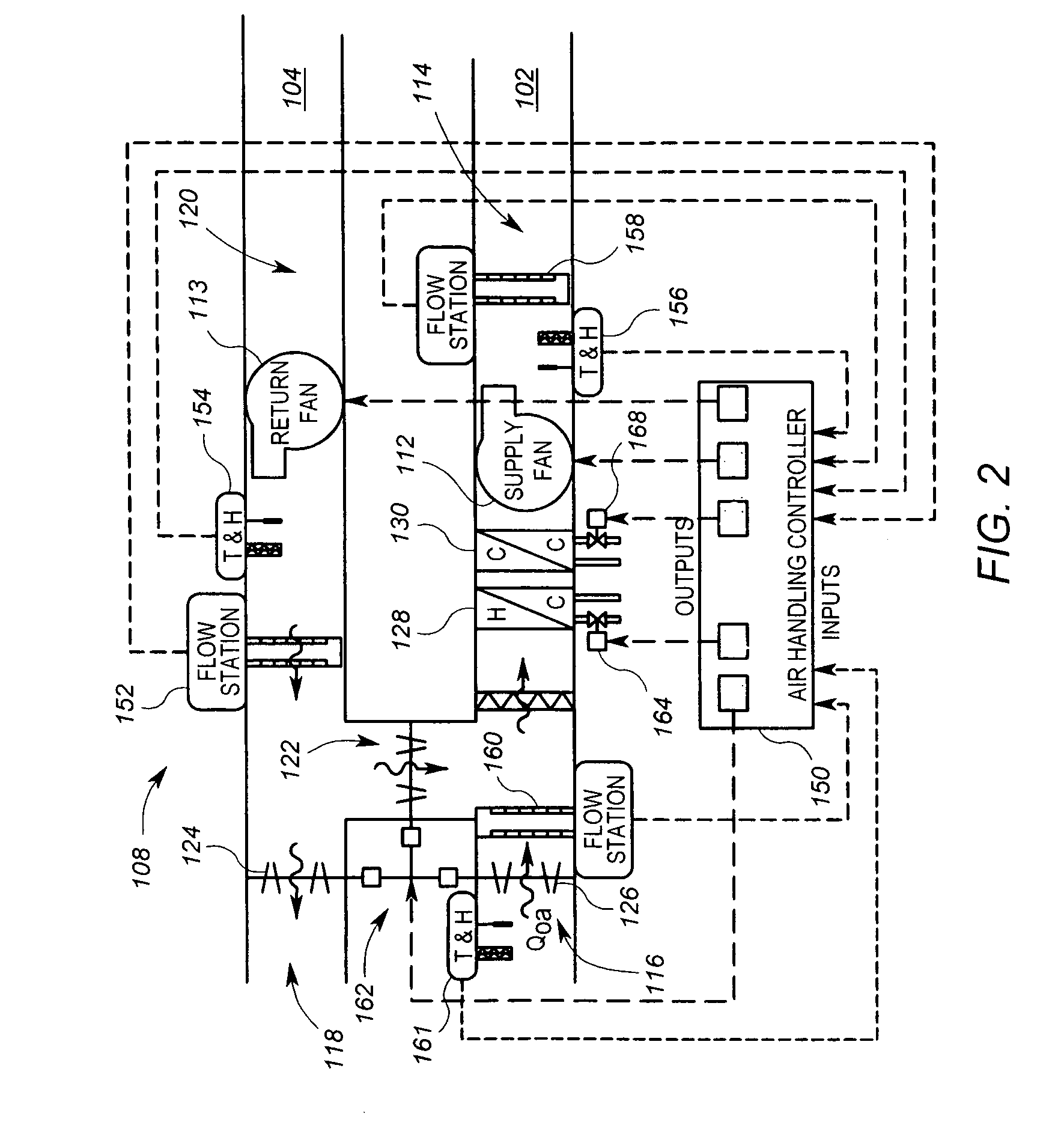
[0182] In step 405, a select control operation of the air handling unit 108 for which a time constant with be estimated is identified. In this example, the cooling coil process is identified. The cooling coil process is the process by which coolant is provided to the cooling coil 130 via the cooling valve actuator 168. The supply air flow passes through the cooling coil 130, and is cooled thereby.

[0183] In step 410, all devices between the controlled device and the temperature sensor are identified. In this example, the controlled device is the cooling coil 130. The only device between the cooling coil 130 and the temperature sensor 156 is the supply fan 112, which is not considered in determining the supply air temperature time constant estimates, as discussed further above. Accordingly, in this example, there are no intermediate devices.

[0184] In step 415, the estimated time constant is calculated by adding the time constants of the actuator of the controlle...

example 2

Heating Coil Process

[0186] For this example, in step 405, the heating coil process is identified. The heating coil process is the process by which a heating medium (e.g. steam or water) is provided to the heating coil 128 via the heating valve actuator 164. The supply air flow passes through the heating coil 128, and is heated thereby.

[0187] In step 410, all devices between the controlled device and the temperature sensor are identified. In this example, the controlled device is the heating coil 128. Apart from the supply fan 112, the only device that is between (i.e. within the flow stream between) the heating coil 128 and the temperature sensor 156 is the cooling coil 130. Because the supply fan 112 is not considered an intermediate device, the only intermediate device is the cooling coil 130 in this example.

[0188] In step 415, the estimated time constant is calculated by adding the time constants of the actuator of the controlled device (heating valve actuator 164), controlled...

example 3

Damper Process

[0191] In step 405, the damper process is identified. The damper process consists of simultaneously moving the dampers 122, 124 and 126. When the dampers 124 and 126 are further closed and the damper 122 is further opened, more recirculated air is passed through the system and less fresh air is passed through the system. If, in such a case, the recirculated air is cooler than the fresh air, then the supply air temperature TS will tend to be reduced. The damper process relates to the time constant for temperature changes to occur as a result of changes in the damper positions.

[0192] In step 410, all devices between the controlled device and the temperature sensor are identified. In this example, the controlled device is the set of dampers 122, 124 and 126, which typically are operated as a unit. Apart from the supply fan 112, the devices between the dampers 122, 124, 126 and the temperature sensor 156 include the cooling coil 130 and heating coil 128. Accordingly, in ...


PUM

PropertyMeasurementUnit
time constantaaaaaaaaaa
time constant TCccaaaaaaaaaa

Abstract

An arrangement for use in connection with an air handling unit includes a controller and a processing circuit. The controller is configured to control a device within an air handler unit, which includes at least a first coil. The processing circuit is configured to receive first information representative of a maximum liquid flow rate through the first coil and second information representative of a maximum air flow rate of the first coil. The processing circuit is further configured to generate a time constant estimate, based on the first information and second information, for use in the controller in performing control of the device.

Description

[0001] This application claims the benefit of U.S. provisional patent application Ser. No. 60 / 731,889, filed Oct. 31, 2005 and which is incorporated herein by reference.FIELD OF THE INVENTION [0002] The invention relates generally to control arrangements in an air handling unit of a building system, particularly those that require time constants for performing control operations. BACKGROUND [0003] Control arrangements are used in a variety of applications, including but not limited to various elements of a building comfort system, or heating, ventilation, air conditioning (“HVAC”) system. One device within an HVAC system is an air handling unit. [0004] An air handling unit is typically known as a device that blows heated or chilled air through the ventilation system of a building. A typical air handling unit includes a fan (or other air moving device) and heating and / or cooling coils. The coils are designed to receive a heating material such as steam or hot water, or cooling materia...

Claims


Application Information

Patent Timeline
Patent Type & Authority Applications(United States)
IPC IPC(8): F24F7/00
CPCF24F3/0442Y02B30/767F24F11/008F24F11/83F24F11/84F24F11/63Y02B30/70
Inventor CHENG, GEORGE SHU-XINGAHMED, OSMANPIENTA, WILLIAM THOMAS
Owner GENERAL CYBERNATION GRP INC DBA CYBOSOFT
Why Eureka
Try Eureka