Unit with recovery wheel and economizer and method of control

a technology of economizer and recovery wheel, which is applied in the field of ventilating and air-conditioning units, can solve the problems of requiring considerable fan energy, consuming energy, and affecting the efficiency of the ventilating system,

Active Publication Date: 2016-06-16
SEMCO INC
View PDF8 Cites 27 Cited by
  • Summary
  • Abstract
  • Description
  • Claims
  • Application Information

AI Technical Summary

Benefits of technology

[0017]Various embodiments further include a power exhaust bypass damper, for example, that opens to allow at least part of the exhaust air to exit the unit through the exhaust air discharge fan without passing through the recovery wheel. In a number of such embodiments, for example, the power exhaust bypass damper is between the exhaust air discharge fan and the exhaust air passageway in (e.g., extending through) the economizer section. In various embodiments, when the power exhaust bypass damper is open, return air from the return air plenum serving the unit is allowed to exit the exhaust air passageway through the power exhaust bypass damper, through the exhaust air discharge fan, and through the exhaust air outlet, for example, without passing through the recovery wheel. Further, in a number of embodiments, when the power exhaust bypass damper is closed, return air from the return air plenum serving the ventilating unit is substantially prevented from exiting the exhaust air passageway through the exhaust air outlet without passing through the recovery wheel.

Problems solved by technology

But adding or removing heat or humidity (moisture) typically involves the expenditure of energy.
Even with recovery devices such as recovery wheels, HVAC systems still use a considerable amount of energy, including both for moving air (fan power) and further conditioning of supply air.
Such prior art units and systems, however, required considerable fan energy to pull air through the return air damper.
In addition, prior art units and systems have included economizers, but under certain conditions, economizer operation has resulted in supply air that has an undesirable level of humidity, making occupants uncomfortable even when indoor air temperature is within parameters.

Method used


Image

  • Unit with recovery wheel and economizer and method of control
  • Unit with recovery wheel and economizer and method of control
  • Unit with recovery wheel and economizer and method of control

Examples


Embodiment Construction

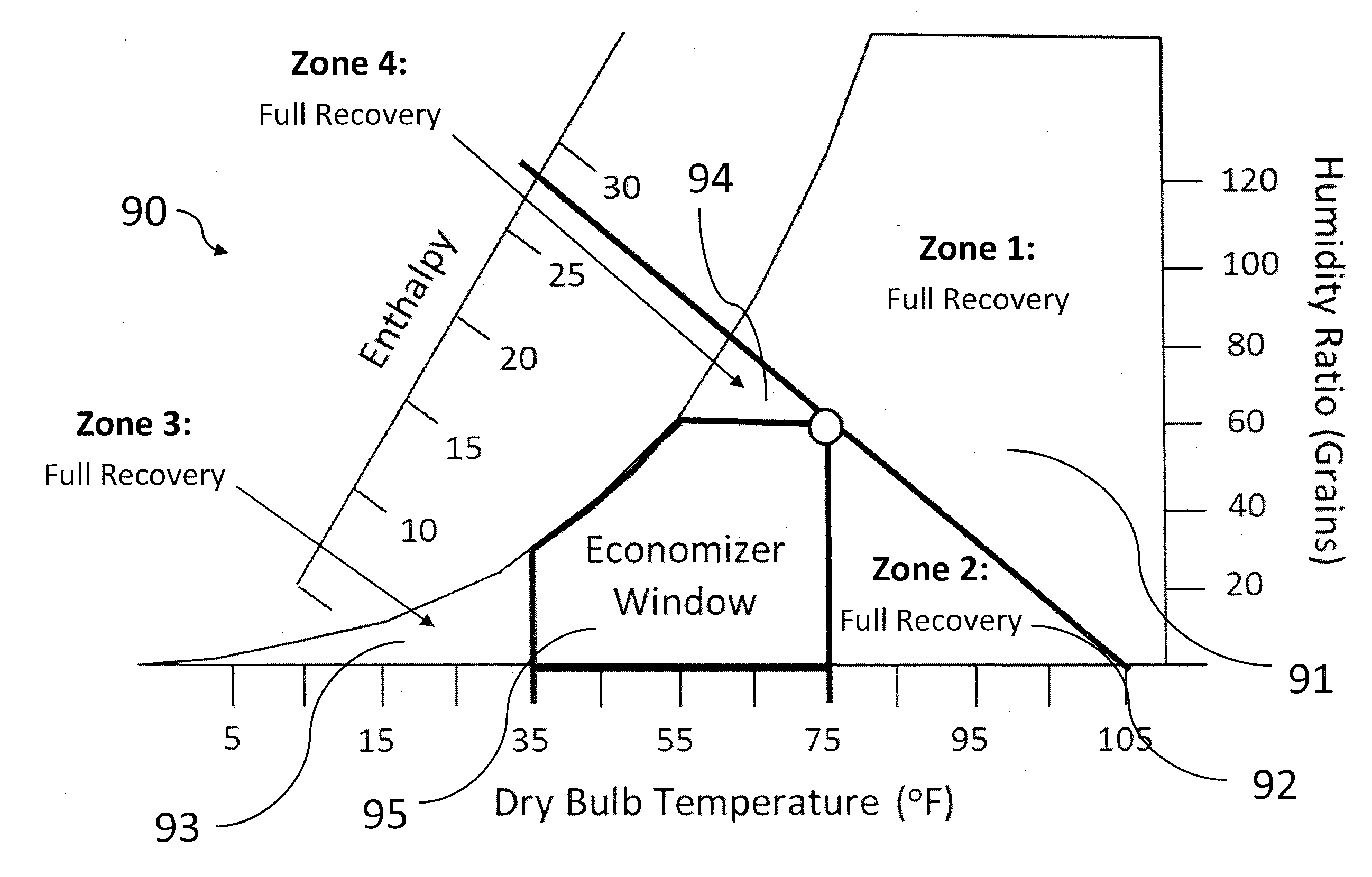
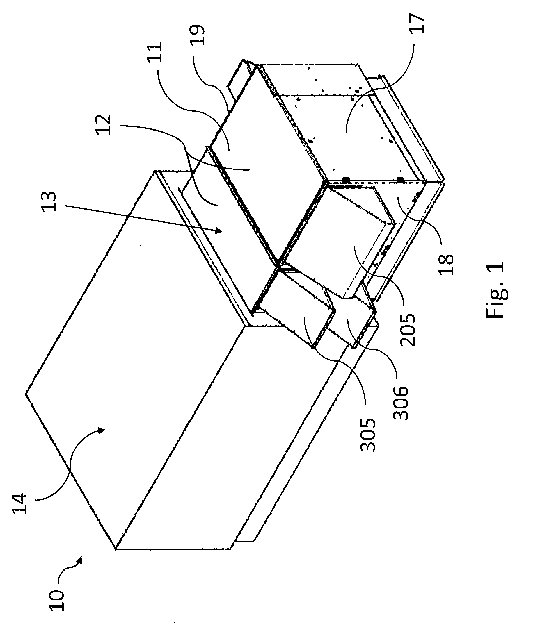
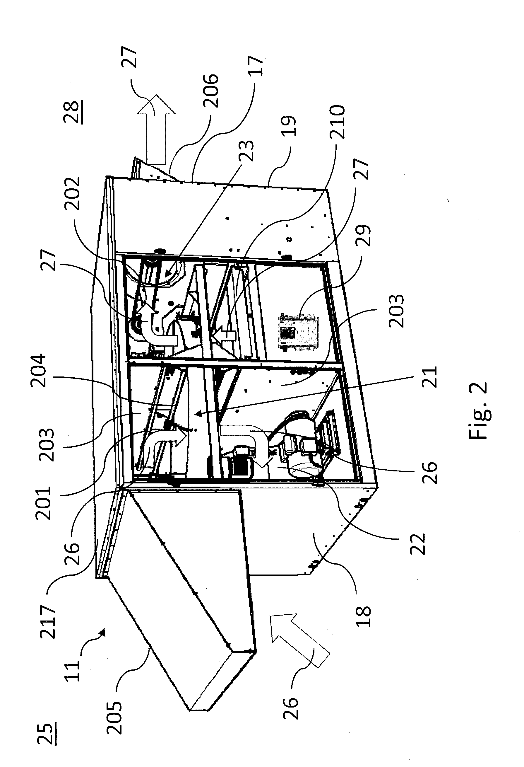
[0008]This invention provides, among other things, various units (e.g., ventilating units, HVAC units, or air conditioning units) that include a recovery wheel, an economizer, and an economizer damper. Various embodiments require no return air damper. Further, certain units include two or at least two (i.e., separate) fans, for example, at least two of an outdoor air supply fan, an exhaust air discharge fan, and an air handler supply fan. Still further, particular units use or compare a dew point, an enthalpy, or both to determine whether to run the economizer. This invention also provides various methods, for example, of controlling airflow in an HVAC unit, for instance, having a recovery wheel and an economizer. Some such methods include, as examples, controlling (e.g., opening and closing) an economizer damper under certain circumstances, for instance, based on different temperatures, enthalpies, dew points, or a combination thereof.

[0009]Various embodiments provide, for example,...


PUM


Abstract

Ventilating units that include a recovery wheel, a supply air outlet from the wheel, an outdoor air supply fan that moves outdoor air through the recovery wheel, an economizer damper that opens to bring outdoor air directly into the supply air outlet, and an exhaust air discharge fan that moves exhaust air through the recovery wheel and to outdoors; HVAC units that include air conditioning with an air handler supply fan, a recovery wheel, an economizer section, an outdoor air supply fan, and controls; and methods of controlling airflow in an HVAC unit that include controlling an economizer damper based on outdoor and return air temperature and enthalpy or dew point. Some ventilating units connect to a packaged air handler and other ventilating units include the air handler, cooling coil, and air handler supply fan. Some embodiments include another damper that opens to bypass the recovery wheel for power exhaust.

Description

RELATED PATENT APPLICATIONS[0001]This patent application is a non-provisional patent application of, and claims priority to, U.S. provisional patent application No. 62 / 092,023, filed Dec. 15, 2014, titled: AIR CONDITIONING UNIT WITH RECOVERY WHEEL AND ECONOMIZER, which has the same inventors and assignee. The contents of this priority provisional patent application are incorporated herein by reference. If there are any conflicts or inconsistencies between this patent application and any documents incorporated by reference herein, however, this patent application governs herein.FIELD OF THE INVENTION[0002]Various embodiments of this invention relate to ventilation and air conditioning units that include both a recovery wheel and an economizer, methods of controlling or configuring such a unit, and methods of reducing the energy consumption, increasing the effectiveness, or both, of an air conditioning unit.BACKGROUND OF THE INVENTION[0003]Heating, ventilating, and air-conditioning (H...

Claims


Application Information

Patent Timeline
Patent Type & Authority Applications(United States)
IPC IPC(8): F24F11/00F24F3/044
CPCF24F11/0001F24F3/044F24F11/0012F24F2011/0016F24F2011/0006F24F2011/0013F24F2011/0002F24F3/1423F24F2203/104F24F11/30F24F2110/10F24F2110/12F24F2110/22F24F2110/60F24F11/52F24F11/77F24F11/84F24F11/46F24F11/86Y02B30/56Y02B30/70
Inventor FISCHER, JOHN C.MITCHELL, RICHARD K.
Owner SEMCO INC
Why Eureka
Try Eureka