

Multiple-Pump Dispenser
a dispenser and pump technology, applied in the field of multi-pump dispensers, can solve the problems of high cost of pumping and expensive dispensers
- Summary
- Abstract
- Description
- Claims
- Application Information
AI Technical Summary
Benefits of technology
Problems solved by technology
Method used
Image

Examples
Embodiment Construction
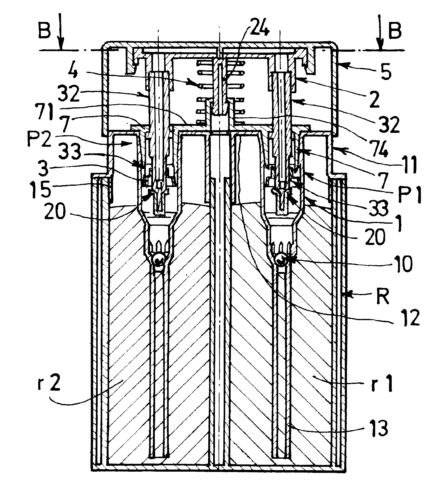
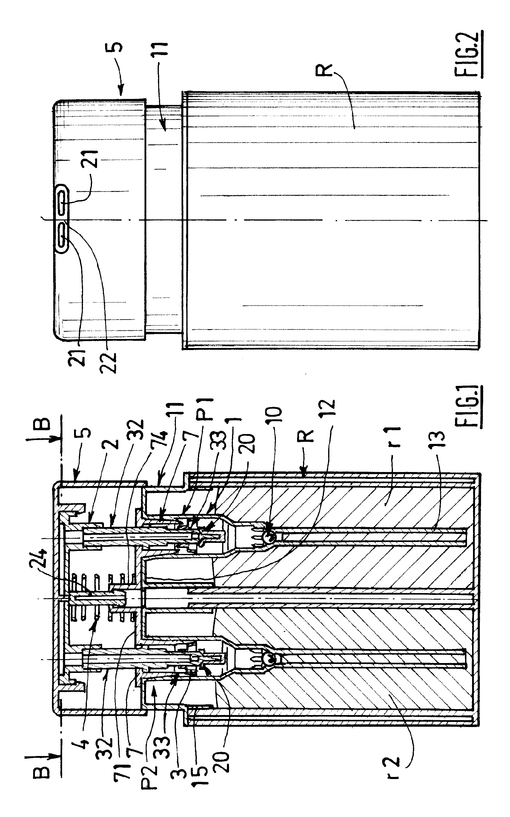
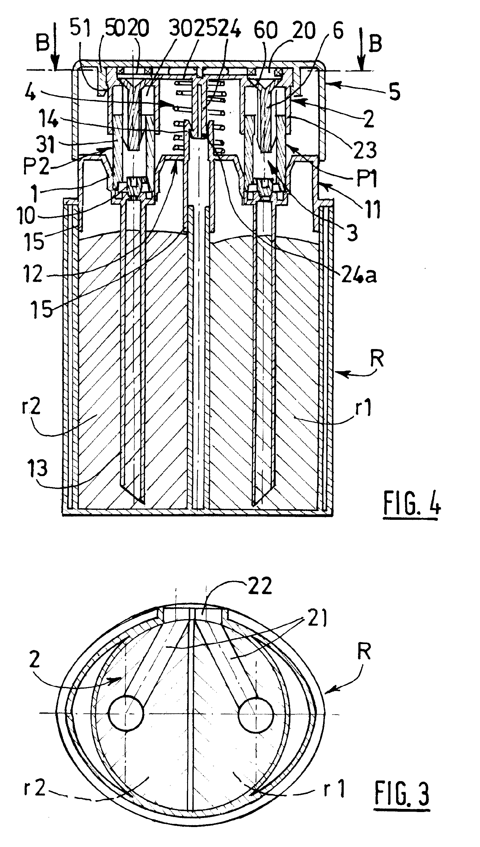
[0038]The distributor shown in the figures comprises a container R equipped with several independent compartments and, in this case, with two semicylindrical compartments r1, r2, each associated with a pump P1, P2.
[0039]Each compartment / pump assembly is adapted for a specific component of a final product to be supplied in the form of a mix or as different products (references 1 and 2 in the figures).
[0040]The pumps P1, P2 usually consist of a body, which is blocked, at the bottom, by a suction valve 10 and, at the top, by an applicator 2 and / or an exhaust valve 20. The bodies 1 contain piston mechanisms 3 which cooperate with at least one elastic return system 4.
[0041]In the embodiments of the invention as shown in FIGS. 1 to 4, the pump bodies 1 are solidly attached to one another in the form of a single shrunk-on ring 11 by a linking spacer 12 which also covers the compartments r1, r2 of the container R in a watertight manner.
[0042]The bodies 1 generally have a tapered cylinder sh...
PUM
 Abstract
Description
Claims
Application Information