Method and Apparatus for Measuring Current

a current measurement and current technology, applied in the direction of magnetic measurement, electrical testing, instruments, etc., can solve the problem that the rogowski coil does not physically recreate the theoretical closed loop of the theoretical rogowski principl

Active Publication Date: 2007-12-20
LEM HEME
View PDF7 Cites 50 Cited by
  • Summary
  • Abstract
  • Description
  • Claims
  • Application Information

AI Technical Summary

Benefits of technology

[0031] Preferably, the conductor comprises at least a first curved section and a second curved section and wherein t

Problems solved by technology

However, since there must be a physical gap between the wire of the coil in the first end and second end of the flexible

Method used


Image

  • Method and Apparatus for Measuring Current
  • Method and Apparatus for Measuring Current
  • Method and Apparatus for Measuring Current

Examples


Embodiment Construction

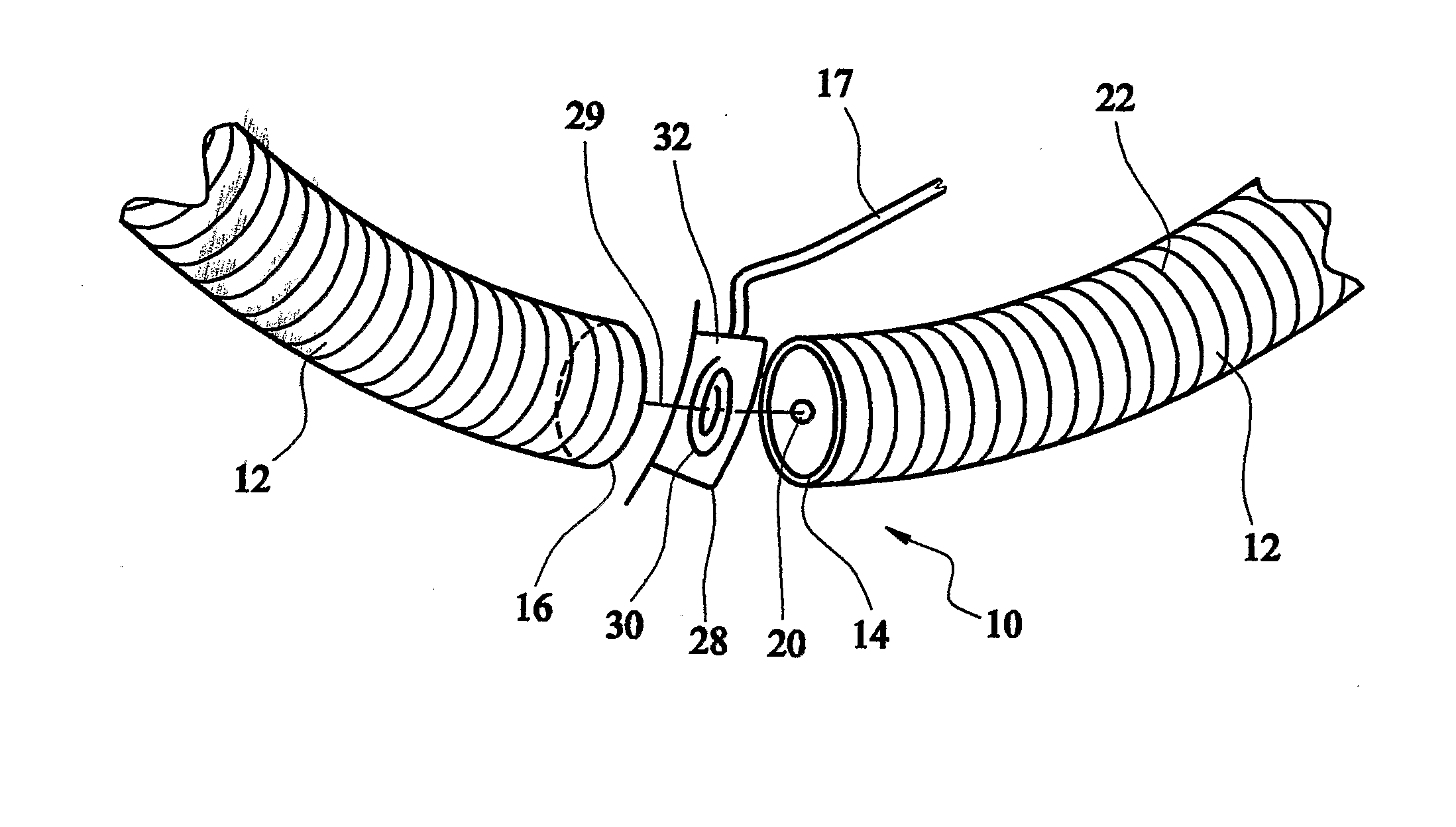
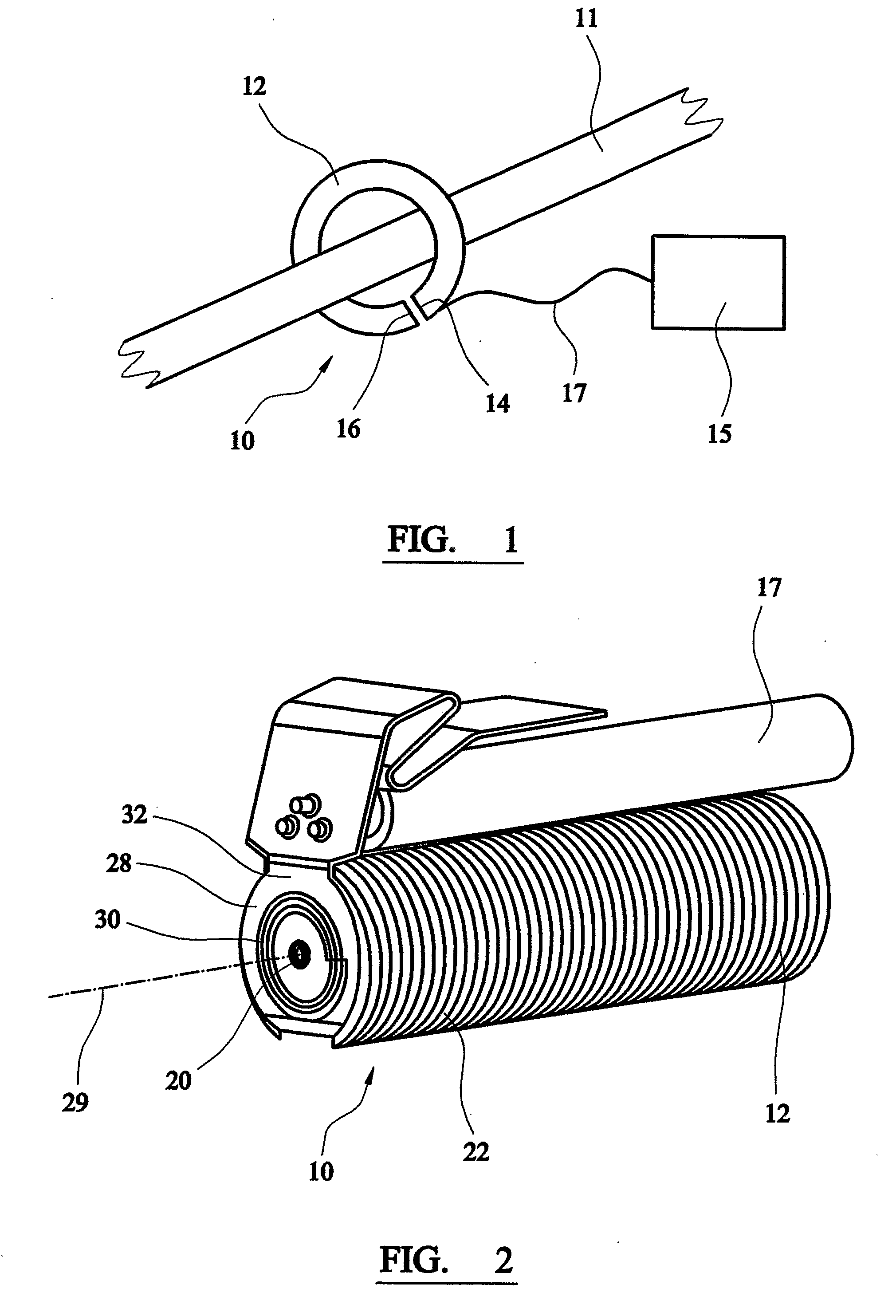
[0038] As shown in FIG. 1, current testing / measuring apparatus 10 comprises a flexible member 12 having a first end 14 and a second end 16. The current measuring apparatus 10 co-operates with calculation means 15 through a cable 17 in order for the calculation means to calculate the current in the conductor 11 from the signal obtained from the current measuring apparatus 10. In use, the flexible member 12 is arranged to locate around a conductor 11 carrying a current to be measured. The first end 14 of the flexible member 12 is arranged, in use, to locate adjacent to the second end 16 of the flexible member in order for the flexible member 12 to form a contiguous loop.

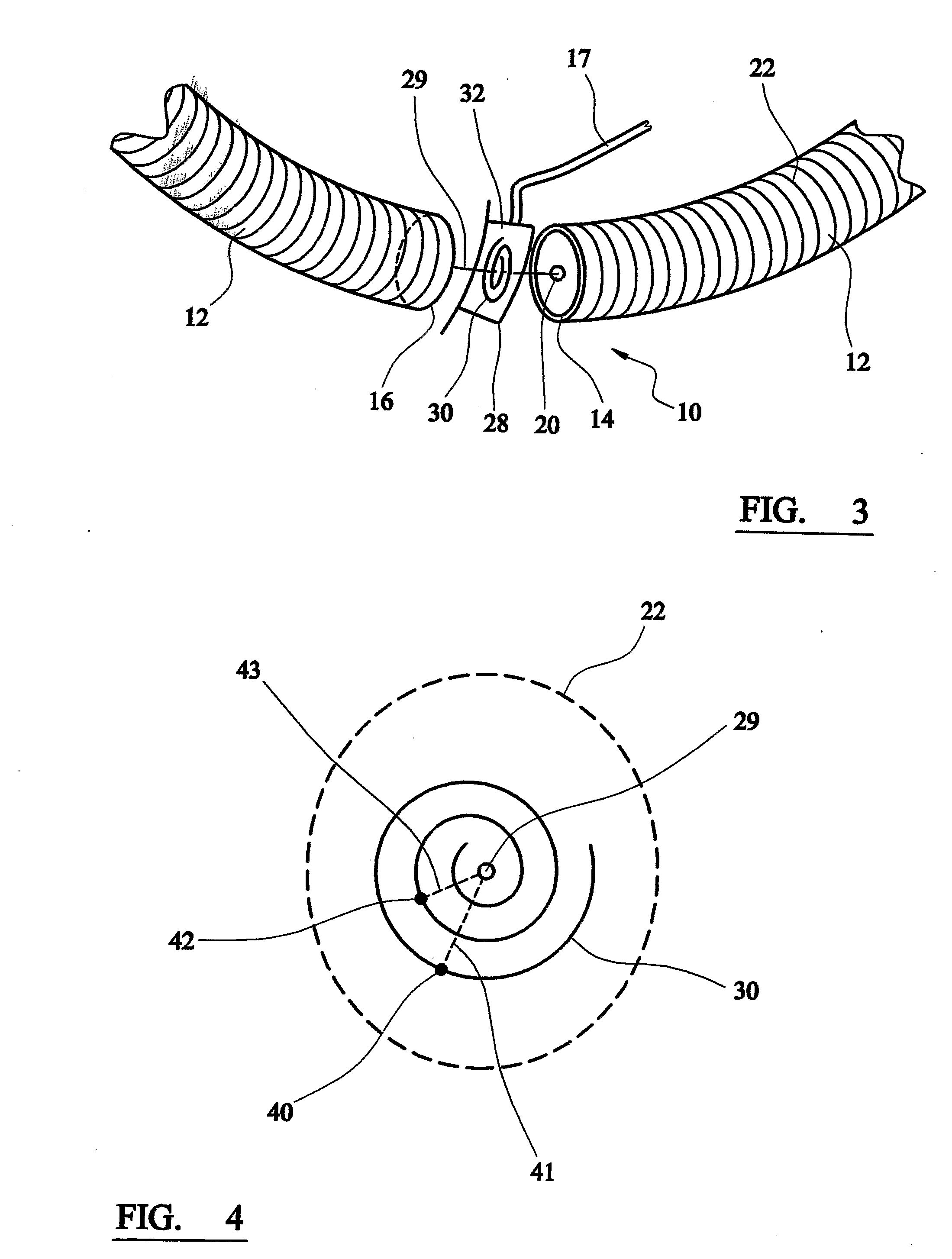
[0039] As shown in FIG. 2 and FIG. 3, the current measuring apparatus 10 comprises a Rogowski coil which includes a central conductor 20 and an outer coil 22 of wire or other conducting material. The Rogowski principle states that if a uniform coil is wound on a non-magnetic former of constant cross-sectional area and...


PUM


Abstract

Current testing/measuring apparatus 10 comprises a flexible member 12 having a first end 14 and a second end 16. In use, the flexible member 12 is arranged to locate around a conductor 11 carrying a current to be measured. In particular, the current measuring apparatus 10 comprises a Rogowski coil. The ends of the flexible member 12 are coupled together in use but a gap is created between the ends. This distance can generate errors in the current measurement and the present invention provides compensation means 28 in the form of a compensation windings. The compensation windings comprise a planar spiral conductor provided on a printed circuit board to compensate for the separation distance between the first end and the second end.

Description

FIELD OF THE INVENTION [0001] The present invention relates to compensation means for current measuring apparatus, current measuring apparatus comprising compensation means, a method of compensating current measuring apparatus and a method of measuring current in a conductor. BACKGROUND TO THE INVENTION [0002] Current measuring apparatus include a uniform coil of wire which is wound on a non-magnetic former of constant cross-section area and shaped into a closed loop. Such current measuring apparatus is termed a Rogowski coil which is based on the Rogowski principle. The Rogowski coil comprises a flexible open ended member which is formed into a contiguous loop around a conductor in order to measure the electric current and associated parameters of the conductor. [0003] In use, the flexible member is located around a conductor in order for a first end of the flexible member to locate adjacent to and be coupled with a second end of the flexible member. Accordingly, the flexible membe...

Claims


Application Information

Patent Timeline
IPC IPC(8): G01R19/00G01R15/14G01R15/18
CPCG01R15/181G01R15/18
Inventor MAHON, JAMES STEPHEN
Owner LEM HEME
Why Eureka
Try Eureka