Parts combining structure, and electronic apparatus

a technology of electronic equipment and combining structure, which is applied in the direction of electrical equipment casings/cabinets/drawers, instruments, portable computers, etc., can solve the problems of time and labor, restricted direction of fixing the resin part to the metallic part,

Inactive Publication Date: 2007-12-20
KK TOSHIBA
View PDF3 Cites 31 Cited by
  • Summary
  • Abstract
  • Description
  • Claims
  • Application Information

AI Technical Summary

Benefits of technology

[0008]In this conventional configuration, the through holes to insert the pins are simple round holes penetrating the metallic part in the thickness direction. Thus, when fixing the resin part to the metallic part, the pins must be inserted into the through holes in the axial direction. As a result, the direction of fixing the resin part to the metallic part is largely restricted. Therefore, time and labor are required for fixing the resin part to the metallic part.

Problems solved by technology

As a result, the direction of fixing the resin part to the metallic part is largely restricted.
Therefore, time and labor are required for fixing the resin part to the metallic part.

Method used


Image

  • Parts combining structure, and electronic apparatus
  • Parts combining structure, and electronic apparatus
  • Parts combining structure, and electronic apparatus

Examples


first embodiment

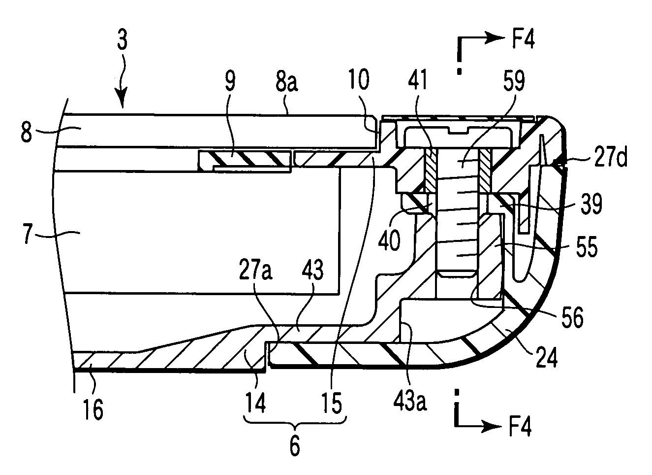
[0111]According to the invention, the slits 47 for insertion of the first projections 28 of the first antenna cover 24 are formed at the distal end edges of the tongue pieces 44, and has the opening width to permit insertion of the first projections 28. The through portions 45 for insertion of the second projections 29 of the first antenna cover 24 has the inlets 50 formed at the front end edges 43a of the first cover support 43. The inlets 50 has the opening width L1 to permit insertion of the second projections 29.

[0112]Therefore, the first projections 28 can be inserted into the slits 47 from the side of the display cover 14. Similarly, the second projections 29 can be inserted into the through portions 45 from the side of the display cover 14.

[0113]In addition, as the slits 47 penetrates the tongue pieces 44, the first projections 28 can be inserted into the slits 47 from the axial direction. As the through portions 45 penetrates the first cover support 43 of the display cover 1...

third embodiment

[0137]FIG. 28 shows the invention.

[0138]The through portion 45 of the third embodiment has a pair of open side edge portions 81a and 81b connecting the inlet 50 and the terminal end 51. The opening width L2 of the terminal end 51 is wider than the opening width L1 of the inlet 50. The open side edge portions 81a and 81b are inclined to be close to each other in the direction from the terminal end 51 to the inlet 50. By this inclined structure, the through portion 45 is made wider in the direction from the inlet 50 to the terminal end 51.

[0139]In the above configuration, when the heating head is pressed to the second projection 29, the molten resin 29a flows into the clearance between the second projection 29 and the through portion 45, and coagulates there at the same time as shown in FIG. 28. As the open side edge portions 81a and 81b of the through portion 45 are inclined in the direction of inserting the second projection 29, the coagulated resin is hung on the open side edges 81...


PUM

PropertyMeasurementUnit
structureaaaaaaaaaa
widthaaaaaaaaaa
electric fieldaaaaaaaaaa

Abstract

A parts combining structure is provided with first part having thermoplastic projection, and a second part having through portion to insert the projection. By thermally crushing the distal end of the projection projecting from the through portion, the first part and second part are combined. The through portion of the second part include inlet opened in the outer peripheral edge of the second part. The inlet has an opening width to permit insertion of the projection.

Description

CROSS-REFERENCE TO RELATED APPLICATIONS[0001]This application is based upon and claims the benefit of priority from Japanese Patent Application No. 2006-170443, filed Jun. 20, 2006, the entire contents of which are incorporated herein by reference.BACKGROUND[0002]1. Field[0003]One embodiment of the invention relates to a structure of combining a synthetic resin part and a metallic part, for example. In particular, the embodiment of the invention relates to an electronic apparatus such as a portable computer having a metallic housing covered by a synthetic resin cover, for example.[0004]2. Description of the Related Art[0005]Recently, an electronic apparatus having an antenna element for radio communication contained in a housing have been available in various types. In such an electronic apparatus, it is necessary to eliminate a factor to disturb an electric field radiated from an antenna element for stabilizing radio communication.[0006]Therefore, in an electric apparatus having a ...

Claims


Application Information

Patent Timeline
Patent Type & Authority Applications(United States)
IPC IPC(8): H01L21/8244
CPCG06F1/1616G06F1/1637G06F1/1698G06F1/1679G06F1/1656
Inventor SHIGENOBU, NAOYAWADA, KOHEISUZUKI, YASUYUKIMIURA, YOSUKE
Owner KK TOSHIBA
Why Eureka
Try Eureka