Multilayer gasket with segmented integral stopper feature

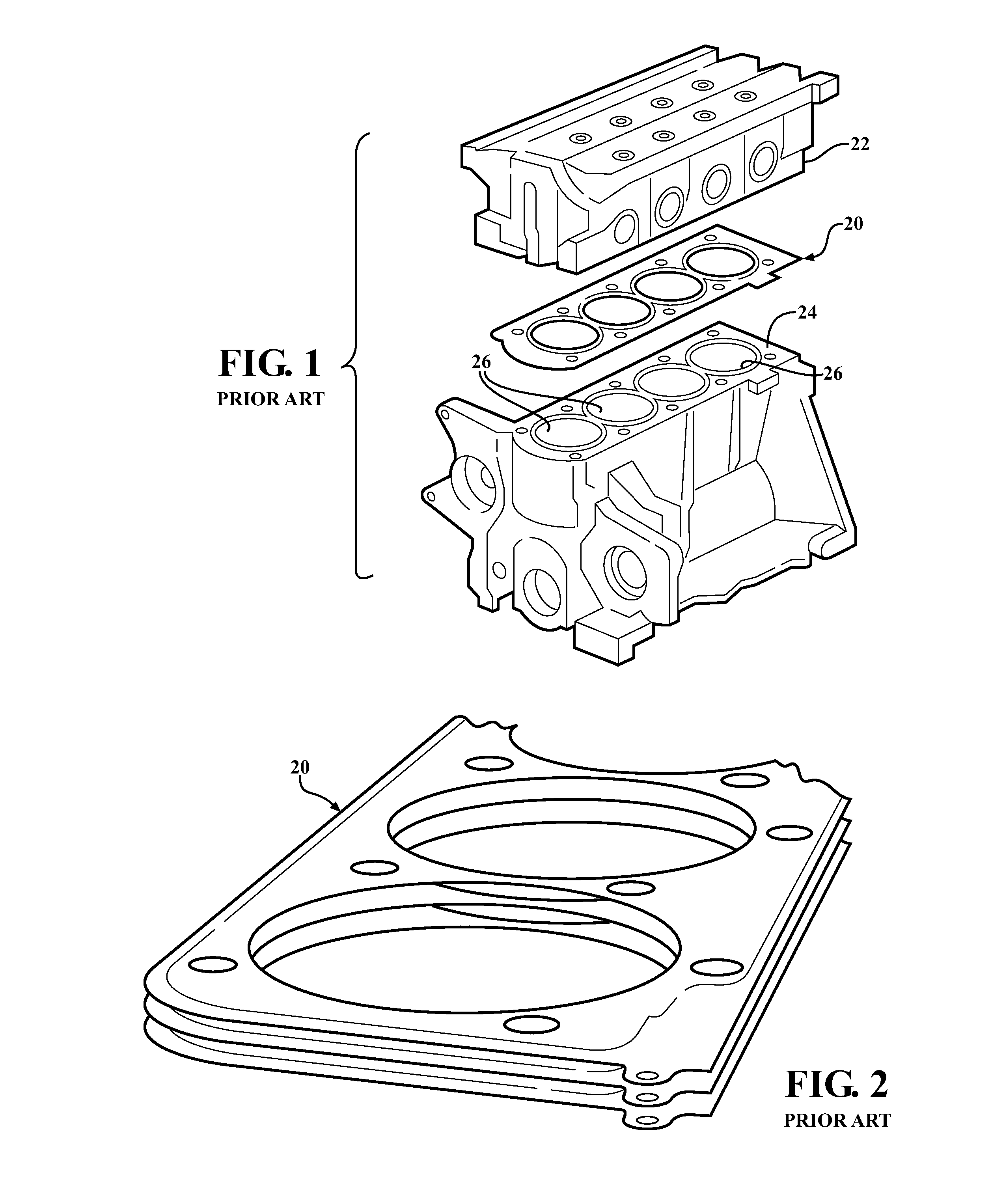
a technology of stopper feature and multi-layer gasket, which is applied in the direction of engine seals, sealing arrangements, machines/engines, etc., can solve the problems of loss of engine efficiency, difficult sealing of combustion gases, and one of the shortcoming of many prior art multi-layer gasket designs

Inactive Publication Date: 2013-12-31
FEDERAL MOGUL MOTORPARTS LLC
View PDF46 Cites 2 Cited by
  • Summary
  • Abstract
  • Description
  • Claims
  • Application Information

AI Technical Summary

Benefits of technology

[0008]A multilayered gasket assembly is provided of the type for sealing around a passage or chamber formed between two mating members. The mating members may, for example, comprise a cylinder block and cylinder head for an internal combustion engine. The gasket assembly includes a first functional layer having at least one first opening. The first functional layer includes a resilient and compressible first sealing bead spaced apart from and surrounding the first opening. The first functional layer includes a first stopper region adjacent the first sealing bead. A second functional layer is provided having at least one second opening. The second functional layer includes a resiliently compressible second sealing bead spaced apart from and surrounding the second opening. The second functional layer includes a second stopper region adjacent the second sealing bead. The first functional layer overlies the second functional layer so that the respective first and second openings are generally aligned with one another and so that the respective first and second stopper regions are generally aligned with one another. The first sealing bead and the second sealing bead are configured to, in use, resiliently oppose one another. A stopper feature is disposed in the stopper region of at least one of the first and second functional layers for the purpose of limiting compression of the first and second functional layers toward each other in use. The stopper feature operates to restrict the first and second sealing beads to partial compression. The stopper feature includes a plurality of discrete nesting embossments formed integrally from at least one of the first and second functional layers. Each nesting embossment is closely spaced to but not touching the next adjacent discrete nesting embossment in a radially overlapping relationship. The discrete nesting embossments can be easily manufactured directly from either or both of the first and second functional layers thereby obviating the need for a complex fold-over stopper or a separately manufactured, loose-piece stopper member as is common in prior art constructions.

Problems solved by technology

The constant transition between compression and expansion in adjacent cylinders creates substantial cyclic pressure differentials that make sealing combustion gases difficult.
As a result, it is common for some combustion gases to leak through the multiple layers of the gasket 20 over time, resulting in some loss of engine efficiency.
One shortcoming of many prior art multilayer gasket designs may be attributed to the high cost of the stopper feature which is typically either formed of integral folds or separately formed and then attached by laser welding or some other technique.
Both the fold-over stoppers and loose piece formation stoppers increase manufacturing costs, material handling complexities and increase manufacturing time.

Method used


Image

  • Multilayer gasket with segmented integral stopper feature
  • Multilayer gasket with segmented integral stopper feature
  • Multilayer gasket with segmented integral stopper feature

Examples


Embodiment Construction

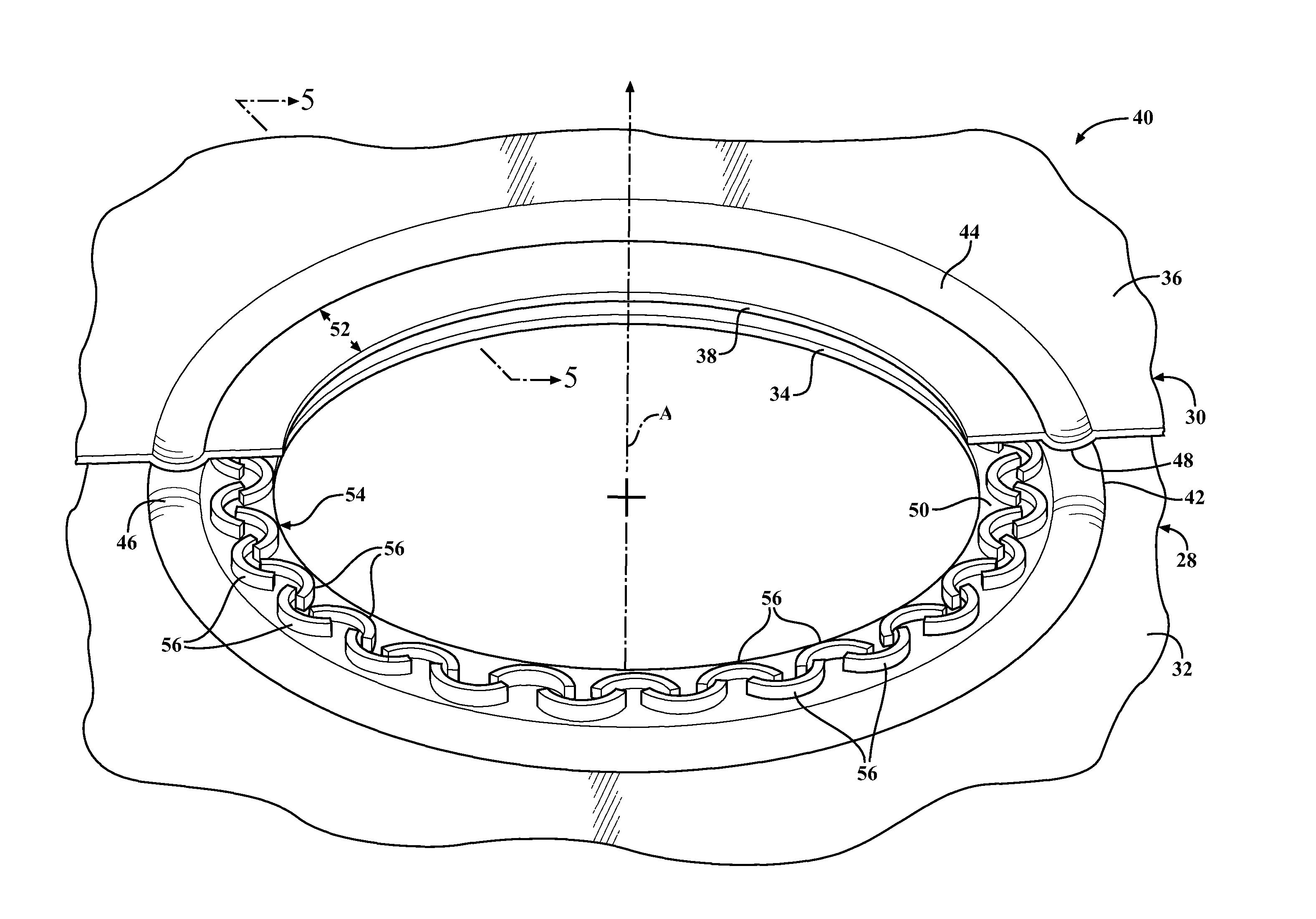
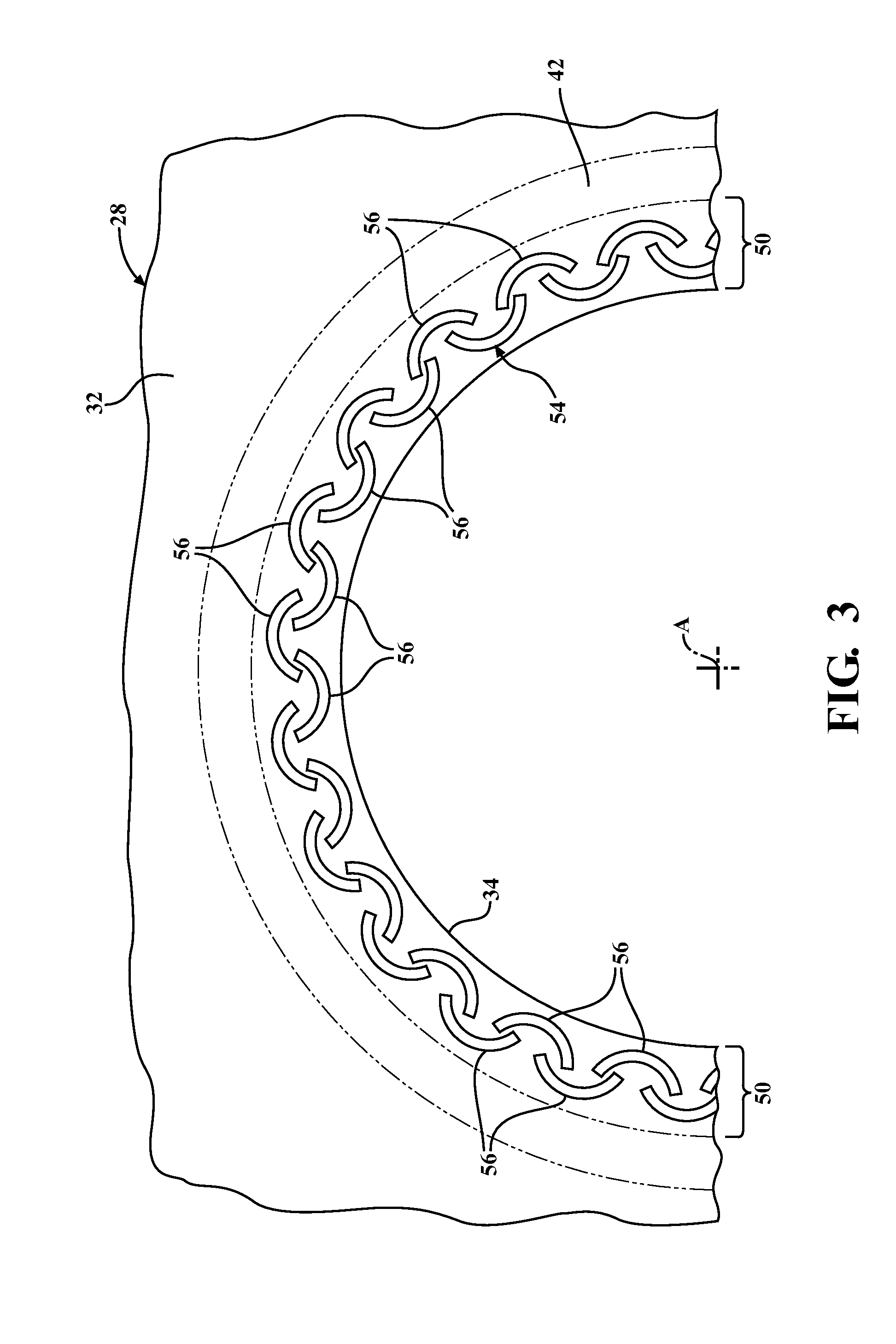
[0020]Referring to the figures wherein like numerals indicate like or corresponding parts throughout the several views, a multilayer gasket according to one embodiment of this invention is generally shown at 40 in FIGS. 3-5. The gasket assembly 40 includes a first functional layer, generally indicated at 28, and a second functional layer, generally indicated at 30. The first functional layer 28 comprises a generally planar body 32 having a generally uniform thickness formed from a sheet of suitable metallic material. A first opening 34 is formed in the first layer 28 for sealing around a shared passage between the two mating members, such as around a combustion chamber opening 26 between the cylinder head 22 and block 24. The second functional layer 30 may be similar in construction to the first layer 28 and also comprises a generally planar second body 36 and a second opening 38. Assembled together as a unit, the first 28 and second 30 layers form the gasket assembly 40. In the ass...


PUM


Abstract

A multilayer metal gasket (40) having first (28) and second (30) functional layers. Each layer (28, 30) includes an opening (34, 38). Sealing beads (42, 44) are formed in each layer (28, 30) and, preferably, arranged to contact each other in crest-to-crest orientation to perfect a seal therebetween. A stopper feature (54) is provided to restrict compression of the sealing beads (42, 44) in use. The stopper feature (54) is arranged in a generally circular pattern and is composed of a plurality of discrete nesting embossments (56) which are closely spaced to one another but do not touch. Each discrete nesting embossment (56) is substantially identical in shape to the next adjacent discrete nesting embossment (56) but oriented approximately 180 degrees therefrom. The embossments (56) may be formed entirely on one of the functional layers (28, 30) or on both functional layers.

Description

CROSS REFERENCE TO RELATED APPLICATIONS[0001]None.BACKGROUND OF THE INVENTION[0002]1. Field of the Invention[0003]This invention relates to multilayer gaskets, and more particularly to multilayer metal gaskets including a stopper for limiting compression height of the gasket when installed between two mating surfaces.[0004]2. Related Art[0005]Multilayer metal gaskets, also referred to by some as multilayer steel (MLS) gaskets, are commonly used in static sealing applications that require a fluid-tight seal to be created around a passage shared by two mating members. For example, an MLS gasket, generally indicated at 20 in FIG. 1, may be clamped between a cylinder head 22 and an engine block 24 to perfect a combustion seal around multiple combustion chambers 26 as well as around oil and lubrication passages shared by the two mating members 22, 24. However, multilayer metal gaskets can also be used in other applications, such as to seal an exhaust manifold to an engine block, as well ...

Claims


Application Information

Patent Timeline
Patent Type & Authority Patents(United States)
IPC IPC(8): F02F11/00
CPCF16J15/0825
Inventor LAFRENZ, CHRISTOPHER JLESNAU, IV, EDWARD
Owner FEDERAL MOGUL MOTORPARTS LLC
Why Eureka
Try Eureka