
Axle load control system and a wheel base adjustment system

a technology of axle load control and adjustment system, which is applied in the direction of tractor-trailer combination, transportation and packaging, instruments, etc., can solve the problems of limiting the operation life of chassis components, unsatisfactory front axle overload, and general awareness of i

Inactive Publication Date: 2007-12-27
VOLVO LASTVAGNAR AB
View PDF6 Cites 30 Cited by
  • Summary
  • Abstract
  • Description
  • Claims
  • Application Information

AI Technical Summary

Benefits of technology

[0005] This problem is solved by the invention providing an axle load control system for a load-carrying truck having a front axle and two or more rear axles, the system comprising:
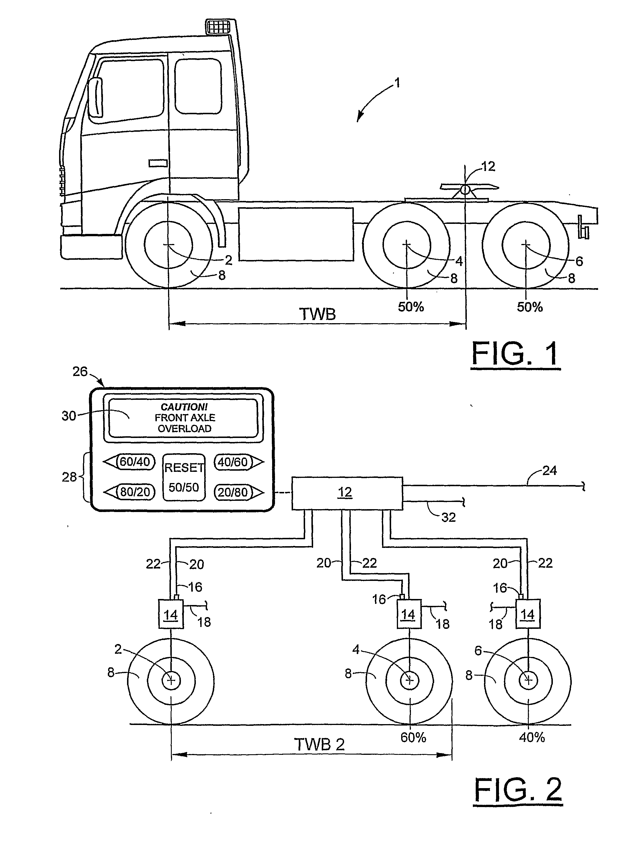
[0017] According to a second aspect of the invention, a further object of the invention is to provide a system of the type mentioned in the introduction, by which system a desired theoretical wheel base of a truck can be obtained. This problem is solved by means of a system according to claim 12. By such a system the wheel base of a truck can be adjusted by transferring load from one rear axle to another. By adjustment of the suspension characteristics of at least one axle the load distribution is altered, and thus the theoretical wheel base is adjusted. Although, this is normally performed by adjustment of at least one rear axle, the theoretical wheel base can be adjusted by adjustment of the suspension characteristics of a front axle if the truck is provided with two front axles.

Problems solved by technology

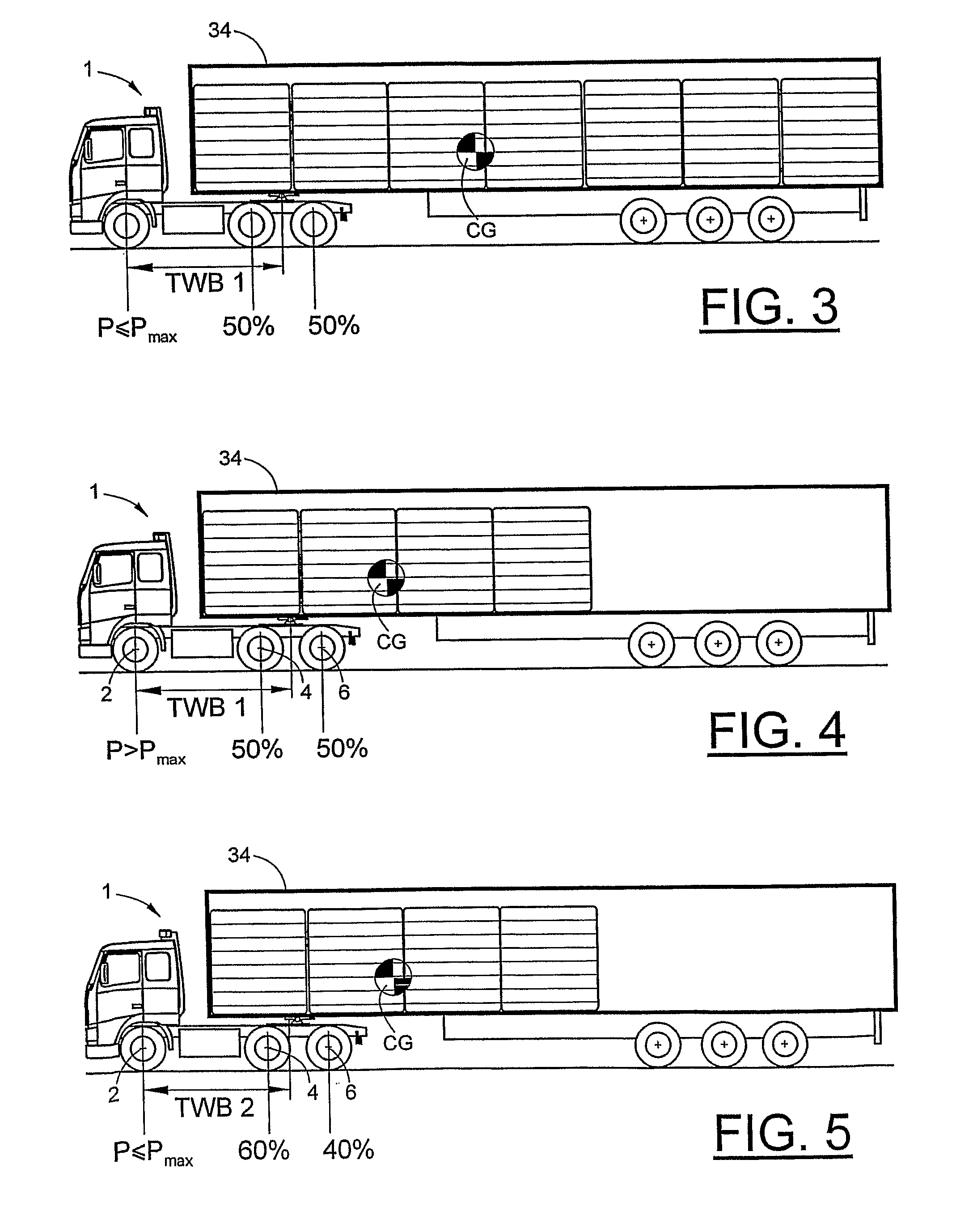
This means that, although the total weight of the vehicle is now lower than it was at the start of the trip, its forward distribution in the truck may lead to an undesired overload of the front axle of the truck.
This undesired front axle overload is a frequently neglected aspect and the general awareness of it is often limited among truck drivers, in spite of the fact that a severely overloaded front axle may pose a serious safety hazard on the road, as well as limiting the operational life of chassis components.

Method used


Image

  • Axle load control system and a wheel base adjustment system
  • Axle load control system and a wheel base adjustment system
  • Axle load control system and a wheel base adjustment system

Examples


Embodiment Construction

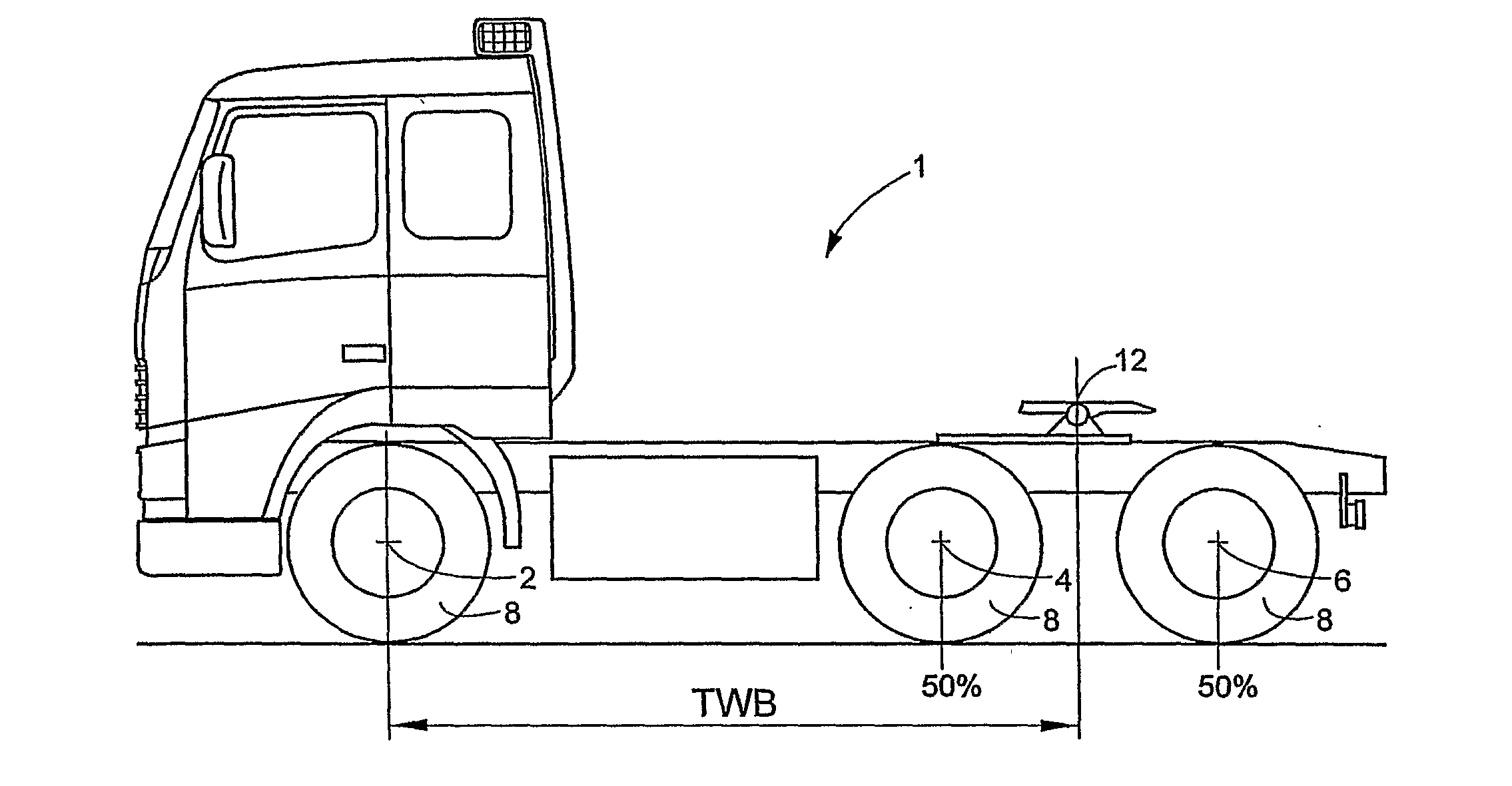
[0031] In FIG. 1, reference numeral 1 generally denotes a load-carrying truck using an axle load control system and / or a wheel base adjustment system according to the invention. In FIG. 1, the truck is represented by a three-axle 6×4 or 6×2 semi-trailer tractor. The truck has a front axle 2 and two rear axles 4, 6 arranged in a tandem configuration, wherein both rear axles are commonly suspended on a pivoting frame (not shown) so that wheels 8 of both rear axles 4, 6 are both constantly in contact with the road. It should, however be noted that the invention is also applicable on any other rear axle combination, such as a boogie combination, wherein one of the rear axles 4, 6 may be lifted so as to lift the wheels 8 of this axle out of road contact if necessary.

[0032]FIG. 1 illustrates the theoretical wheelbase TWB at a 50 / 50 split load distribution on the rear axles 4, 6, i.e. where each rear axle 4, 6 carries 50% of the load on the rear axles. This is the most common fixed load d...


PUM


Abstract

An axle load control system and method for a load-carrying truck having a front axle and two or more rear axles is provided. The system includes a wheel suspension system with a suspension control processor, a load sensor arranged at each of the axles for detecting one or more load indication parameters, the load sensor providing the parameters to the suspension control processor which translates the parameters into actual axle load values for the individual axles. The control processor is arranged to compare the actual axle load values with a predefined maximum allowable axle load value for each axle, and to control—or indicate to a driver the need to control—the wheel suspension system so as to effect an individual adjustment of the suspension characteristics for each axle in such a way that excess axle load on an overloaded axle is transferred to one or more of the remaining axles, thereby adjusting the theoretical wheelbase of the truck.

Description

TECHNICAL FIELD [0001] The present invention relates to an axle load control system and method for a load carrying truck according to the preambles of claims 1 and 8. Furthermore, the invention relates to a system and a method for adjusting the theoretical wheel base according to the preambles of claims of 12 and 18. The invention is applicable to both semi-trailer tractors and rigid trucks. BACKGROUND [0002] Load carrying trucks are generally well adapted and specified for their particular missions and for particular kinds of loads. Modern air suspension systems are smoother and more controllable than more traditional spring suspension systems. Traditionally, however, trucks are optimized for an even axle load distribution when the vehicle is fully loaded. In this situation, the centre of gravity of the truck is generally conveniently located at or near the longitudinal centre of the truck and each axle is loaded well within legal limits for axle load. Thus, once fully loaded, a tr...

Claims


Application Information

Patent Timeline
Patent Type & Authority Applications(United States)
IPC IPC(8): B60G9/00B62D53/06B60GB60G17/015G01G19/08
CPCB60G17/0152G01G19/08B60G2400/61B60G2400/252B60G17/0155B60G17/052
Inventor REGNELL, HANSLILJEBLAD, BENNY
Owner VOLVO LASTVAGNAR AB
Learn More