Device and method for controlling the step size of an adaptive filter

a technology of adaptive filter and step size, which is applied in the direction of transducer acoustic reaction prevention, transmission, electrical apparatus, etc., can solve the problems of not being able to adapt the filter much faster and the majority of these approaches have considerable weaknesses, so as to improve the compensation effect of feedback

Inactive Publication Date: 2007-12-27
SIVANTOS PTE LTD
View PDF1 Cites 14 Cited by
  • Summary
  • Abstract
  • Description
  • Claims
  • Application Information

AI Technical Summary

Benefits of technology

The patent aims to improve the feedback compensation based on the current acoustic situations. The technical effect is to enhance the efficiency and accuracy of the feedback compensation.

Problems solved by technology

The technical problem addressed in this patent text is finding a suitable step size for adaptive filters in hearing aids to compensate for feedback. Different situations require different rates of adaptation, and previous methods have weaknesses when dealing with strongly correlated excitation signals such as music or clinking of glass. The patent proposes a method for controlling the adaptation in real-time based on the presence of feedback.

Method used


Image

  • Device and method for controlling the step size of an adaptive filter
  • Device and method for controlling the step size of an adaptive filter
  • Device and method for controlling the step size of an adaptive filter

Examples


Embodiment Construction

[0024]The exemplary embodiment described in more detail below represents a preferred embodiment of the present invention.

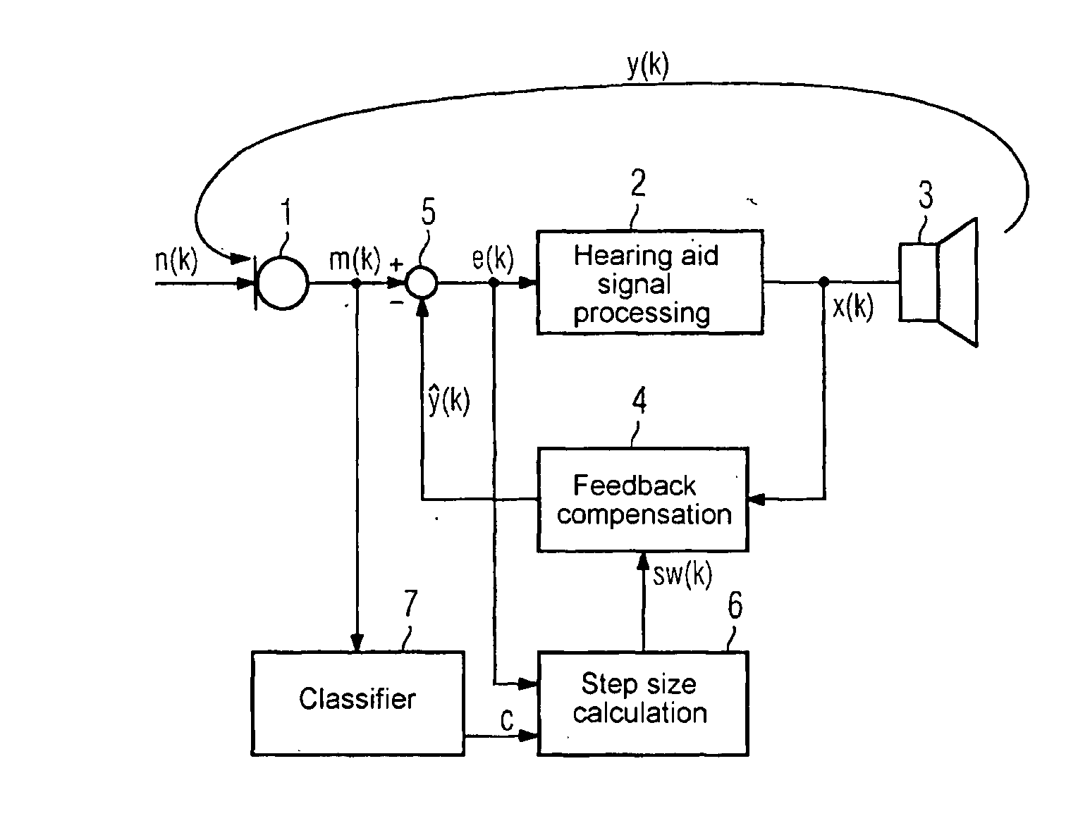
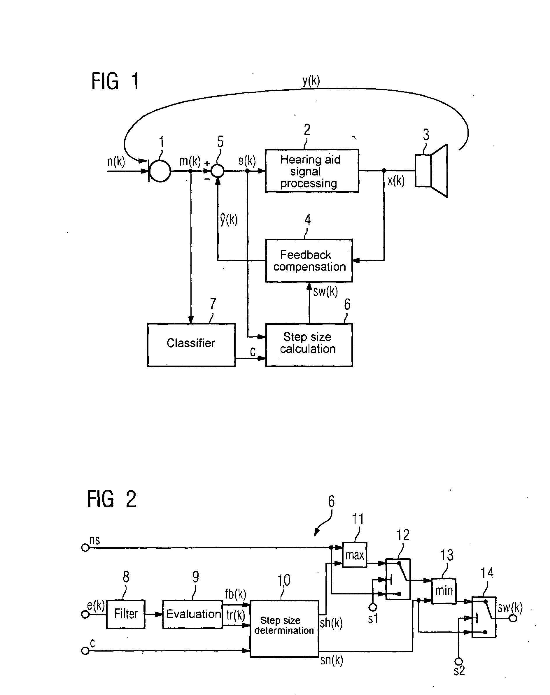
[0025]FIG. 1 shows a hearing aid circuit with a microphone 1, a signal processor 2 and a listening device 3. The signal x(k) emanating from the signal processor 2 is fed back from the listening device 3 to the microphone 1 as signal y(k), where k represents a discrete time index. As well as the feedback signal y(k), the microphone 1 also picks up a useful signal n and outputs a microphone signal m. A feedback compensator 4 picks up the output signal x(k) of the hearing aid signal processor 2 and from this generates an estimated feedback signal ŷ(k). This estimated feedback signal ŷ(k) is subtracted from the useful signal in a subtractor 5, which is located between the microphone 1 and the hearing aid signal processor 2, so that a resulting signal e(k) is produced, which is fed into the hearing aid signal processor 2.

[0026]According to the invention, the signal e(k...


PUM


Abstract

The determination of a suitable step size for controlling the adaptation of a filter of an acoustic feedback compensator especially for hearing aids is to be improved. A step size controller is therefore provided in which an input signal is analyzed in at least two frequency bands. In doing so, any steep signal edges in the individual frequency bands are detected. The adaptation step size of an adaptive filter is then controlled depending on the number of frequency bands in which steep signal edges are detected, wherein the magnitude of the signal edges can be included in the decision.

Description


Claims


Application Information

Patent Timeline
Owner SIVANTOS PTE LTD
Why Eureka
Try Eureka