Adjustable putter

a putter and adjuster technology, applied in the field of golf putters, can solve the problems that the known putter is still short of providing a comprehensive range of customizing with the putter, and achieve the effect of enhancing the clamping speed and clamping for

Inactive Publication Date: 2007-12-27
DYNAFLEX INT
View PDF20 Cites 71 Cited by
  • Summary
  • Abstract
  • Description
  • Claims
  • Application Information

AI Technical Summary

Benefits of technology

[0020]Acute edges are formed along the boundaries of the semi-spherical recesses and semi-circular top openings of both the head and clamp member to bite the frictional sphere of the shaft in the ball joint locally to enhance the clamping speed as well as clamping force.
[0021]The weight element sets in the compact mode cooperate to visualize an aiming body in volume to assist the aiming centerline of the center plate for the golfer to hit the ball consistently.
[0022]The copper stabilization weights are stackable and removable to adjust overall putter head weight and head balance as well as being able to adjust impact feel from firm to soft using a simple tool of a hex driver. With its adjustable geometry, weight, balance, and feel, the present putter allows the golfer to make adjustment to suit personal preferences. The putter is so adaptable that it complements the golfer's own natural way of stroke instead of compromising each unique stroke to fit otherwise less adaptable putters.

Problems solved by technology

As the above patents indicate, known putters are still short of providing a comprehensive range of customizing with putter weight adjustments, loft adjustments, and / or bounce adjustments in an easy structure to make and use intuitively.

Method used


Image

  • Adjustable putter
  • Adjustable putter
  • Adjustable putter

Examples


Embodiment Construction

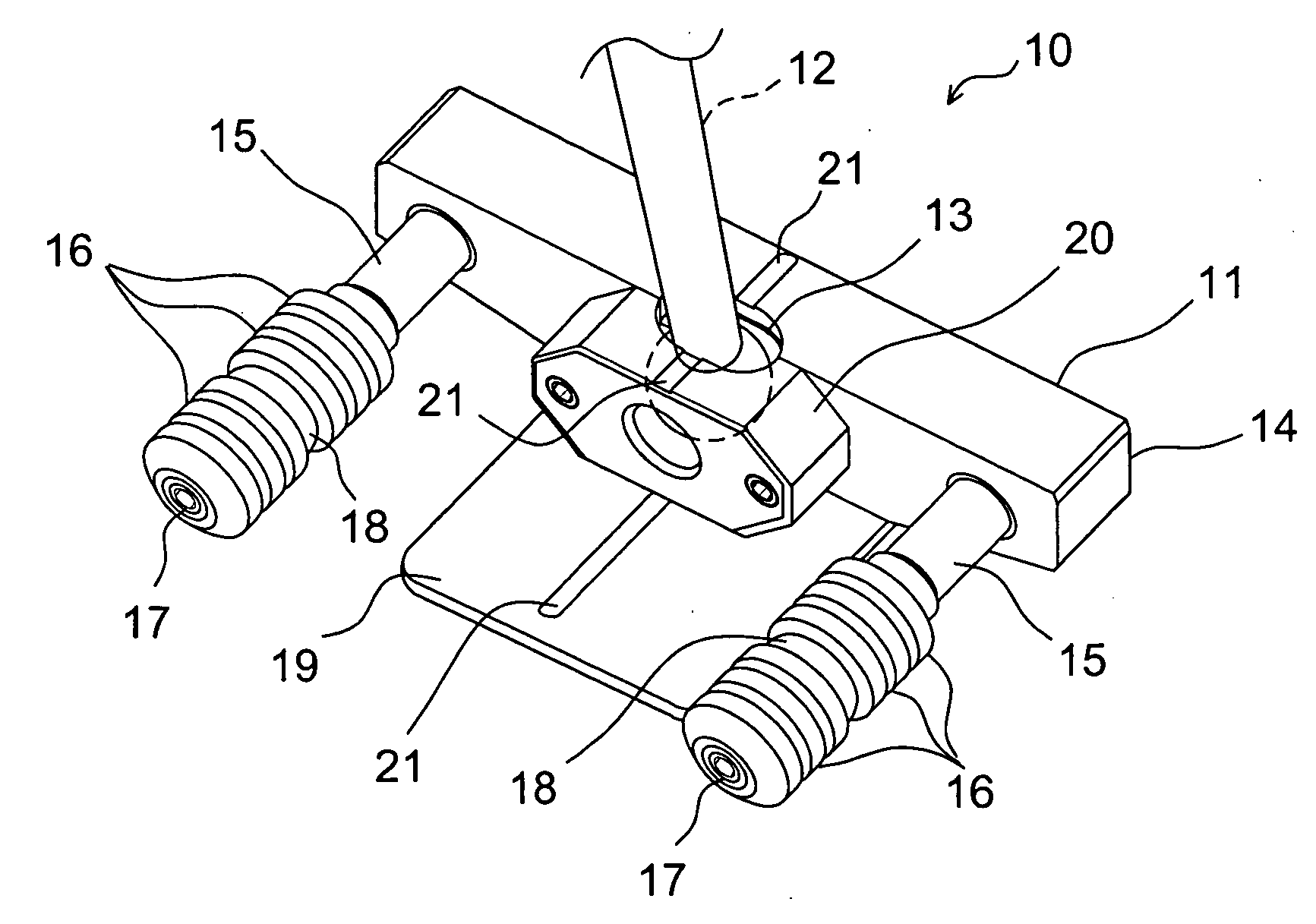
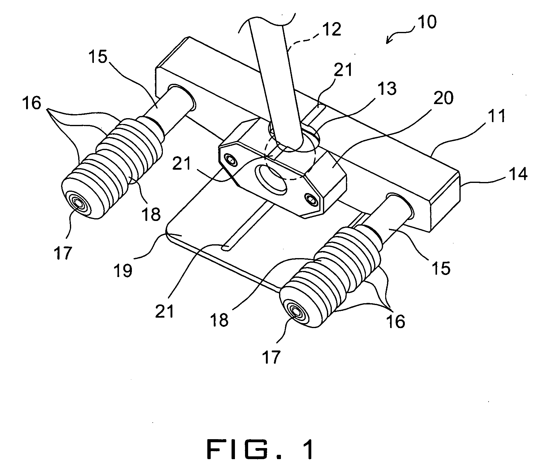
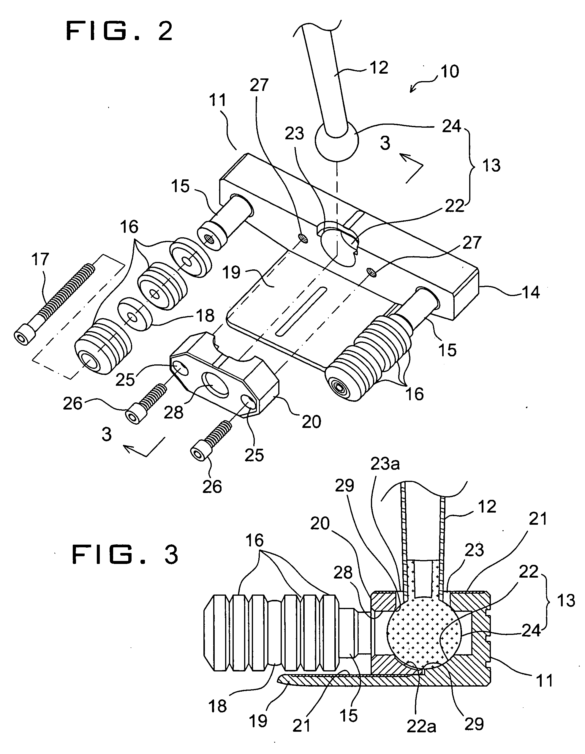
[0039]With reference to FIG. 1, a putter 10 according to a first embodiment of the present invention generally has a head 11 and a shaft 12 connected to the putter head 11 through a ball joint 13. The putter head 11 is a solid metal block having a generally rectangular flat face 14 to hit the ball.

[0040]Extending rearwards of the head 11 are two threaded posts 15 formed integral to the head 11 at opposite ends thereof. Each post 15 supports a stack of stability weights 16, which are varying thickness of heavy bored discs threaded together by socket head screws 17 to the post 15. At least one elastic washer 18 is removably threaded within the weight stack 16 to each post 15 to provide a cushioning effect to the hit ball resulting in an adjusted rebound characteristics of the putter 10 and its feel as well as the overall weight and balance.

[0041]Because of the ball joint 13 of the shaft 12, the putter 10 is adaptable to both left and right-handed addressing. Between the balance posts ...


PUM


Abstract

A golf putter comprises latitudinally elongated head having a generally rectangular hitting face against a golf ball. The head has an integral center plate extending longitudinally and rearward from the hitting face at its bottom. The center plate has a visible centerline for aiming at the ball. A ball joint for angularly fixing a shaft to the head includes a frictional sphere attached to the bottom end of the shaft. A truncated spherical socket is formed by a middle section of the head and a clamp member screw fastened to the head, whereby the shaft is locked in a truncated spherical interior wall at an adjusted angle to the head. Two swappable posts extend from the opposite side of the hitting face of the head near its latitudinal edges, each post having a centrally threaded bore and being threadedly attached to the head so that it may be replaced by a body of varying weight for plugging a void created by the threading of the post.

Description

BACKGROUND OF THE INVENTION[0001]A. Field of the Invention[0002]The present invention relates to golf putters, and more particularly, an adjustable putter for its weighting, lie, loft, grip rotation right or left.[0003]B. Description of the Prior Art[0004]Golf putter is used for short strokes of a ball into a hall cup to complete a hole. This precision instrument of golf club generally consists of a grip, a shaft and a head. The head of the putter is normally designed to have a perpendicular clubface to the playing ground without a significant loft to give the ball a special trajectory.[0005]There are correct methods of using the putter with calm wrists and arms, which in unity should make a pendulum motion sideways resulting in the ball rolling over a distance determined by the gripping force of the hands and the extent of a back swing. Specifically for short putting, wrist or fingers should not be involved in controlling forces to the ball to get the best result. With the well kno...

Claims


Application Information

Patent Timeline
Patent Type & Authority Applications(United States)
IPC IPC(8): A63B53/00
CPCA63B49/06A63B53/02A63B53/0487A63B2053/0433A63B53/065A63B2053/0441A63B2053/0491A63B53/06A63B60/52A63B53/0441A63B53/0433A63B60/00
Inventor DWORZAN, BILL
Owner DYNAFLEX INT
Why Eureka
Try Eureka