Golf club head
a golf club and club head technology, applied in golf clubs, golf, sport apparatus, etc., can solve the problems of insufficient ball flight, insufficient ball gripping or ball holding on the club face, and poor so as to improve the directionality of ball flying and increase the carry distance
Inactive Publication Date: 2007-12-27
DUNLOP SPORTS CO LTD
View PDF2 Cites 18 Cited by
- Summary
- Abstract
- Description
- Claims
- Application Information
AI Technical Summary
Benefits of technology
[0005]It is therefore, an object of the present invention to provide a golf club head in which, by optimizing the head shape in relation to the position of the sweat
Problems solved by technology
Therefor, there is a tendency that even at the time of impact the head can not return to the right address position where the club face is at right angle to the target line (trajectory) of the ball, and so called “ball gripping” or “ball holding” on the club
Method used
View moreImage
Smart ImageViewing Examples
Examples
 PUM
 Abstract
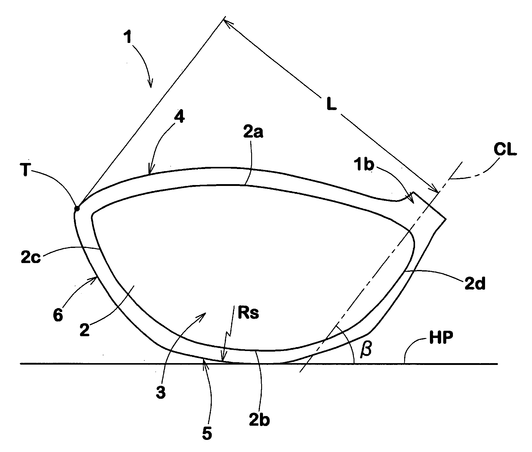
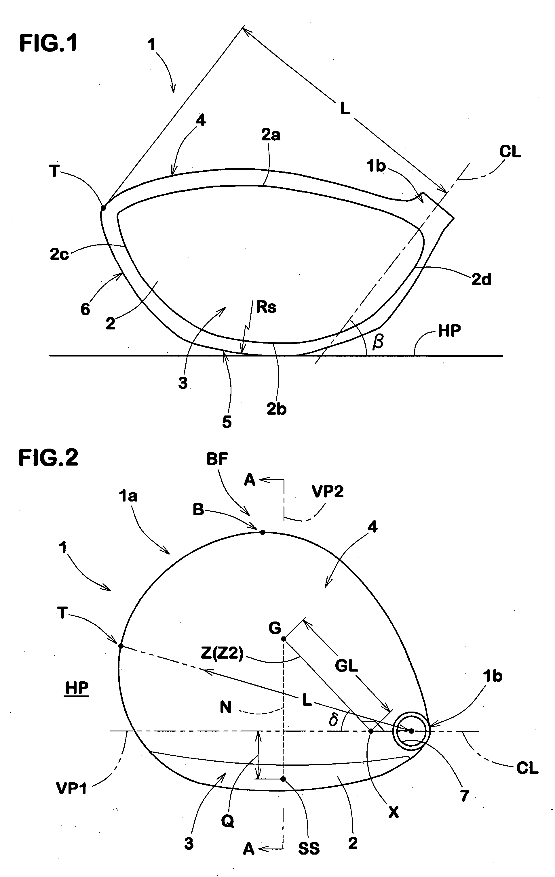
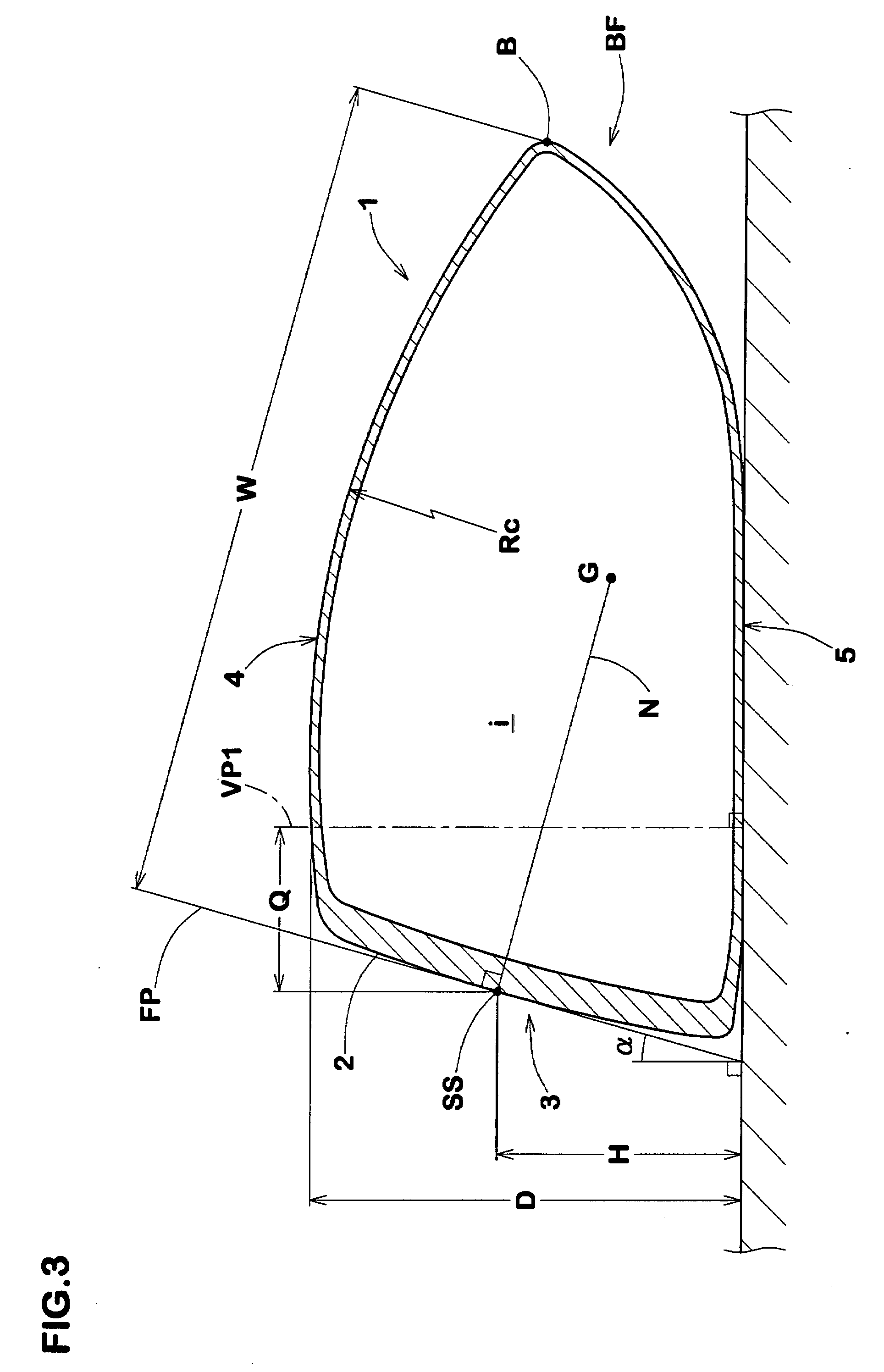
A wood-type golf club head has a hollow shell structure having a head length L (mm), a head-depth W (mm) and a sweet spot height H (mm) which satisfy: 0.80≦W/L≦1.0 and H≦76×(W/L)−31. The head length L is the distance between the clubshaft axis CL and a point T farthest from the clubshaft axis CL. The head depth W is the distance between a plane FP tangent to the sweet spot SS and a point B farthest from the plane FP.
Description
BACKGROUND OF THE INVENTION[0001]The present invention relates to a golf club head, more particularly to a wood-type golf club head having a hollow structure configured to increase the carry distance.[0002]Wood-type hollow golf club heads having various shapes have been proposed.[0003]With respect to the position of the center of gravity of the head, there is a tendency that, when the size of the golf club head in the back-and-forth direction is increased, the distance of the center of gravity from the club face is also increased. Since the club face is usually provided with a loft angle larger than 0 degree, the sweet spot height increases with the increase in the distance of the center of gravity. This will increase the likelihood that the golf ball hits a lower part of the club face under the sweet spot, and the backspin is increased due to the gear effect. As a result, the ball flight tends to become so called “ballooning” or “rising” trajectory due to too much backspin and a re...
Claims
Login to View More Application Information
Patent Timeline
 IPC IPC(8): A63B53/04A63B102/32
CPCA63B53/0466A63B2053/0408A63B2053/0412A63B2053/0437A63B2053/0433A63B2053/0491A63B2209/00A63B2053/0416A63B53/0412A63B53/0437A63B53/0408A63B53/0416A63B53/0433A63B60/02
Inventor OYAMA, HITOSHI
Owner DUNLOP SPORTS CO LTD
Features
- R&D
- Intellectual Property
- Life Sciences
- Materials
- Tech Scout
- Unparalleled Data Quality
- Higher Quality Content
- 60% Fewer Hallucinations
Learn More Browse by: Latest US Patents, China's latest patents, Technical Efficacy Thesaurus, Application Domain, Technology Topic, Popular Technical Reports.
© 2025 PatSnap. All rights reserved.Legal|Privacy policy|Modern Slavery Act Transparency Statement|Sitemap|About US| Contact US: help@patsnap.com


