Golf club shaft

a golf club and shaft technology, applied in the field of shafts, can solve the problems of “heavy” feel during the swing motion and the ball speed does not always increase, and achieve the effects of reducing the rate of head speed reduction, maximizing effect, and increasing head weigh

Inactive Publication Date: 2015-10-22
MITSUBISHI CHEM CORP
View PDF13 Cites 9 Cited by
  • Summary
  • Abstract
  • Description
  • Claims
  • Application Information

AI Technical Summary

Benefits of technology

[0026]A golf club shaft according to one aspect of the present invention and a golf club made of such a golf club shaft are capable of lowering the rate of reduction in head speed relative to a gain in head weight. As a result, when a gain in head weight causes the initial ball speed to increase, the effect is maximized, and carry distance of the ball increases.

Problems solved by technology

However, if the clubhead weight is set greater, the moment of inertia of the club increases, resulting in a “heavy” feel during the swing motion.
However, the problem is that ball speed does not always increase as theoretically predicted.

Method used


Image

  • Golf club shaft
  • Golf club shaft
  • Golf club shaft

Examples


example 1

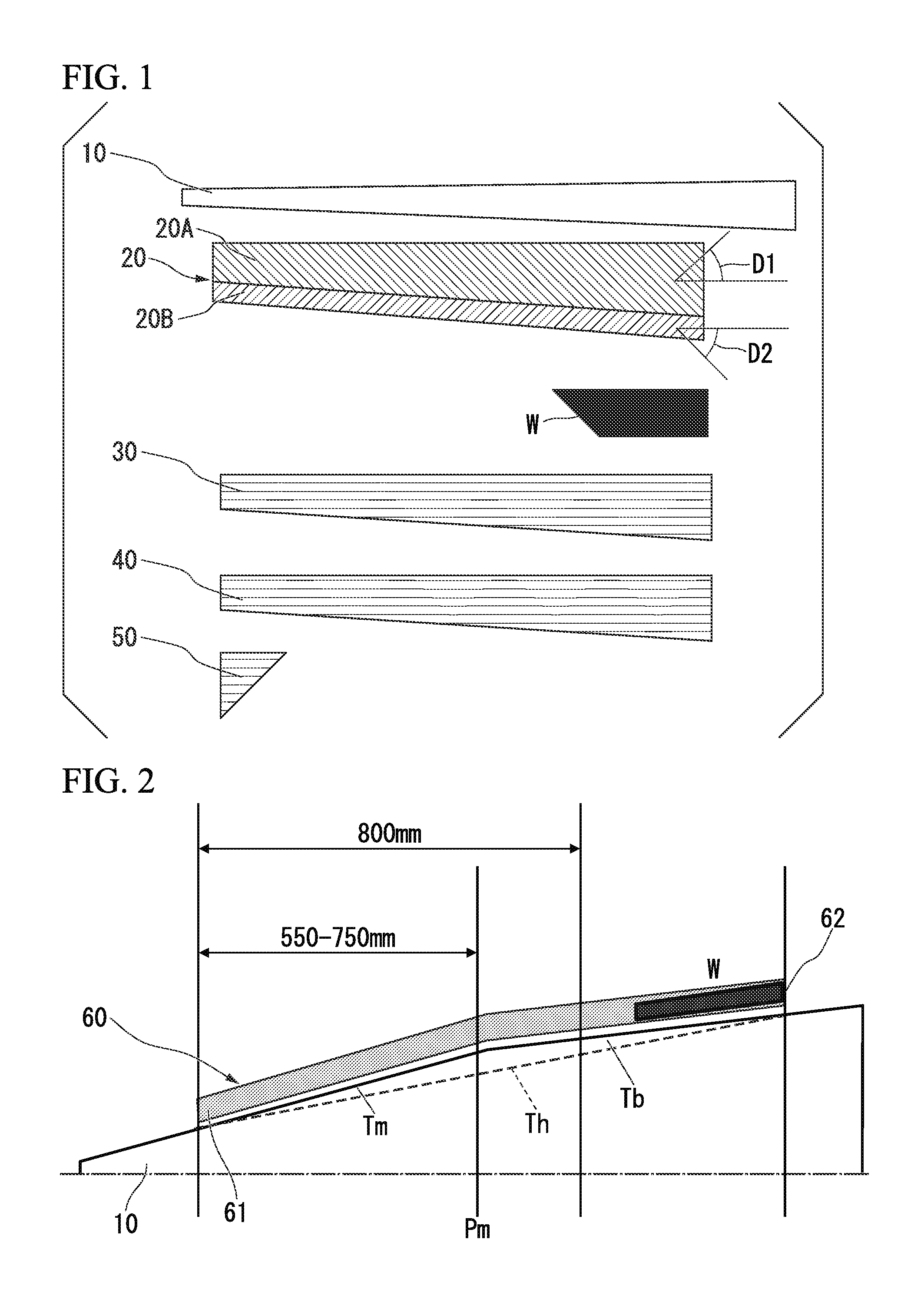
[0106]Example 1 of the present invention is described with reference to FIG. 1. Around the mandrel 10 of FIG. 1 (diameter at the tip end=6.0 mm, diameter at the butt end=13.3 mm), the following layers were wrapped in that order: an angle layer 20 (prepreg K: two sheets of prepreg K were laminated with fiber orientation angles of ±45 degrees to the longitudinal direction of a shaft), a weight layer (W) (prepreg W1: laminated with a fiber orientation angle of zero degrees to the longitudinal direction of a shaft), a first straight layer 30 (prepreg D), a second straight layer 40 (prepreg D), and a tip reinforcement layer 50 (prepreg H: wrapped from the tip end to a point 250 mm upward). After thermosetting the resin, the mandrel 10 was pulled out. Next, a section 10 mm from the tip end and a section 12 mm from the butt end were cut off and the remaining portion was polished. Accordingly, a shaft was obtained to have a full length (LS) of 1168 mm, a narrow-end outer diameter of 8.50 mm...

example 2

[0109]The shaft was produced the same as in Example 1 except that the number of wrappings in the angle layer was changed and the following modification was made to adjust the total weight of the shaft. The number of wrappings in the angle layer was adjusted not only in the present example but in each example. However, that description is omitted.

[0110]The weight percentage of the weight layer (W) was set at 13.5%.

example 3

[0111]The shaft was produced the same as in Example 1 except for the following change.

[0112]The weight percentage of the weight layer (W) was set at 17.0%.


PUM


Abstract

The present invention provides a high-balance-point shaft capable of increasing ball speed. A golf club shaft formed by laminating fiber-reinforced resin, wherein the balance point obtained by formula below is set to be 53% or higher; and the kickpoint obtained by formula below is set to be 44% or higher.

Description

FIELD OF THE INVENTION[0001]The present invention relates to a shaft used for a golf club. The present application is based upon and claims the benefit of priority to Japanese Patent Application No. 2012-191090, filed Aug. 31, 2012. The entire contents of the application are incorporated herein by reference.BACKGROUND ART[0002]Since restitution regulations on golf club heads were added to the rules, various methods have been attempted to compensate for lower restitution at the head. Designing heavier heads is one such attempt. That technology aims to extend carry distance by increasing the clubhead weight so as to increase the kinetic energy of the head during the swing motion.[0003]However, if the clubhead weight is set greater, the moment of inertia of the club increases, resulting in a “heavy” feel during the swing motion. To solve the problem, golf shafts are also being improved, and a so-called high-balance-point shaft, in which the gravity center is shifted closer to the grip,...

Claims


Application Information

Patent Timeline
Patent Type & Authority Applications(United States)
IPC IPC(8): A63B53/10
CPCA63B53/10A63B60/42A63B60/0081
Inventor SHIMONO, SATOSHIKANEKO, TAKASHI
Owner MITSUBISHI CHEM CORP
Why Eureka
Try Eureka