Fishing reel

a reel and reel body technology, applied in the field of fishing reels, can solve the problems of inability to rotate the spool smoothly and lightly (freely), inability to cope with sufficient and positive brake force applied to the spool, and inability to carry out such casting operations as to be able to cope sufficiently and positively, so as to prevent the occurrence of backlash in the spool and extend the carrying distance of the terminal tackles

Inactive Publication Date: 2006-08-08
DAIWA SEIKO CORPORATION
View PDF20 Cites 6 Cited by
  • Summary
  • Abstract
  • Description
  • Claims
  • Application Information

AI Technical Summary

Benefits of technology

[0013]The present invention aims at eliminating the problems found in the above-mentioned conventional fishing reel. Accordingly, it is an object of the invention to provide a fishing reel which is able to adjust finely a brake force to be applied to a spool during rotation of the spool, thereby being able to provide an excellent efficiency in a casting operation, in particular, does not brake the rotation of the spool in a spool rotation rising area ranging from the early stage of the casting operation to the high-speed rotation of the spool, thereby being able not only to extend the carrying distance of the terminal tackles but also to prevent the occurrence of the backlash in the spool.

Problems solved by technology

The backlash raises some troubles: for example, the backlash can cause the different portions of the fishing line to be entwined together, or can cause the fishing line to be inserted into between the outer peripheral portion of the flange of the spool and the reel main body.
However, the conventional centrifugal brake device is structured such that it simply can switch the brake blocks over between the brake operation positions, where they are frictionally contacted with the brake shoe, and the brake non-operation positions where they are moved away from the brake shoe; that is, in the brake operation, since the brake blocks are contacted with the brake shoe instantaneously and with the same force, the brake force to be applied to the spool cannot be adjusted finely.
As a result of this, it is impossible to carry out such casting operation as to be able to cope sufficiently and positively with the varying conditions (such as, the weight of terminal tackles, a distance up to a fishing point, wind, the skill of an angler, and the like) in an actual fishing spot.
Also, in the above-mentioned conventional centrifugal brake device, even in the spool low speed rotation that does not require a brake force (that is, even when the spool is to be rotated freely), the brake blocks can be frictionally contacted with the brake shoe due to the centrifugal force produced in the spool rotation operation, which makes it impossible to rotate the spool smoothly and lightly (freely).
Due to this, the efficiency of the casting operation is degraded.
However, in the structures disclosed in the above-mentioned two publications, since the rotation of the spool is braked from the early stage of the high-speed rotation of the spool, the brake force is applied to the spool before the spool rotation reaches the high-speed rotation in the casting operation early stage (that is, the rising area of the spool rotation) to thereby restrict the rotation of the spool, that is, restrict the initial rotation speed of the spool, with the result that the carrying distance of the terminal tackles cannot be extended.
Therefore, there are still left problems to be solved in these structures when they are used as a spool brake device which not only can extend the carrying distance of the terminal tackles but also can prevent the backlash in the spool.
In the above-cited two conventional structures, because the rotation of the spool is braked from the high-speed rotation early stage of the spool, the rotation speed of the spool is not able to reach the high-speed rotation speed in the casting operation early stage, so that the carrying distance of the terminal tackles cannot be extended.

Method used


Image

  • Fishing reel
  • Fishing reel
  • Fishing reel

Examples


first embodiment

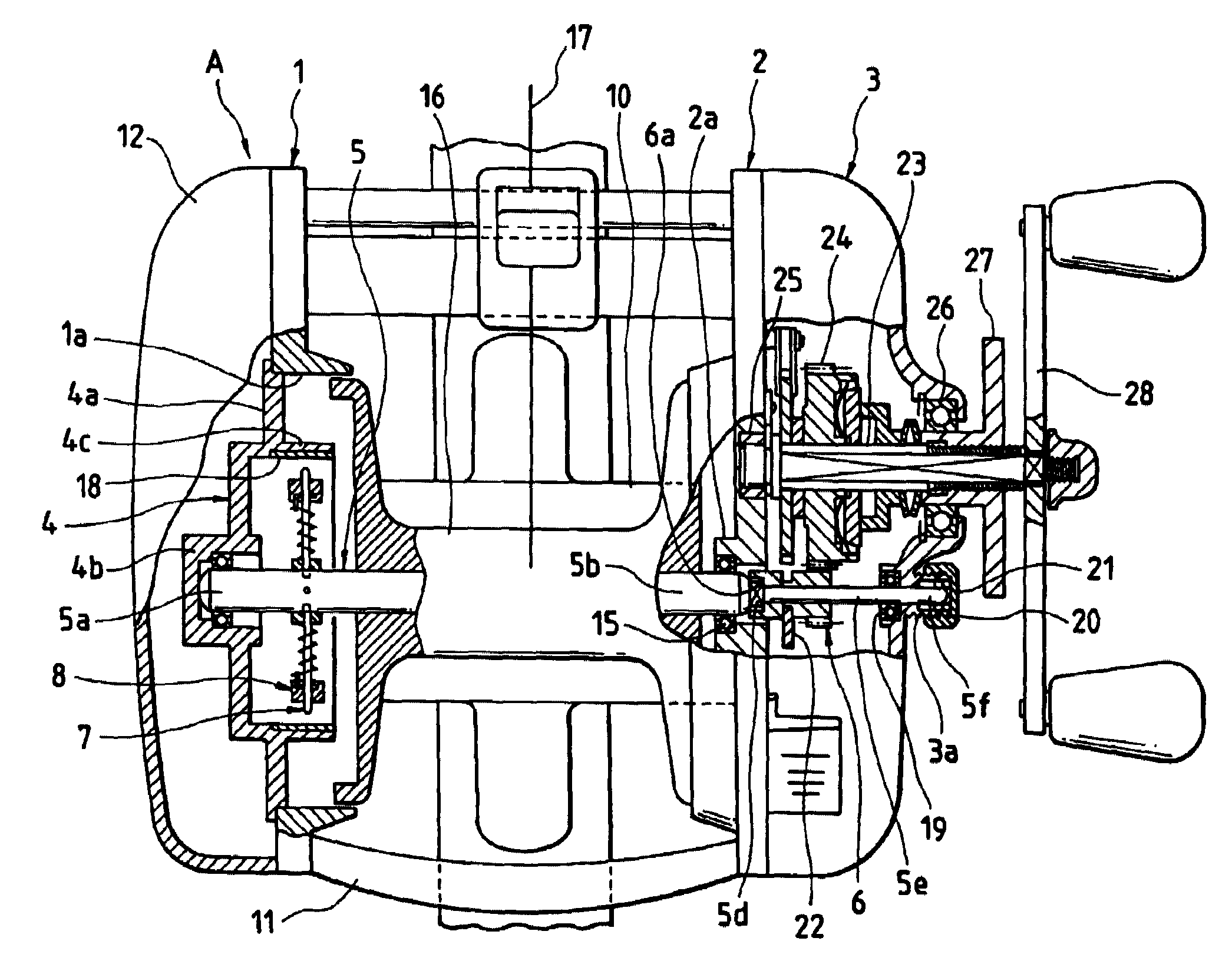
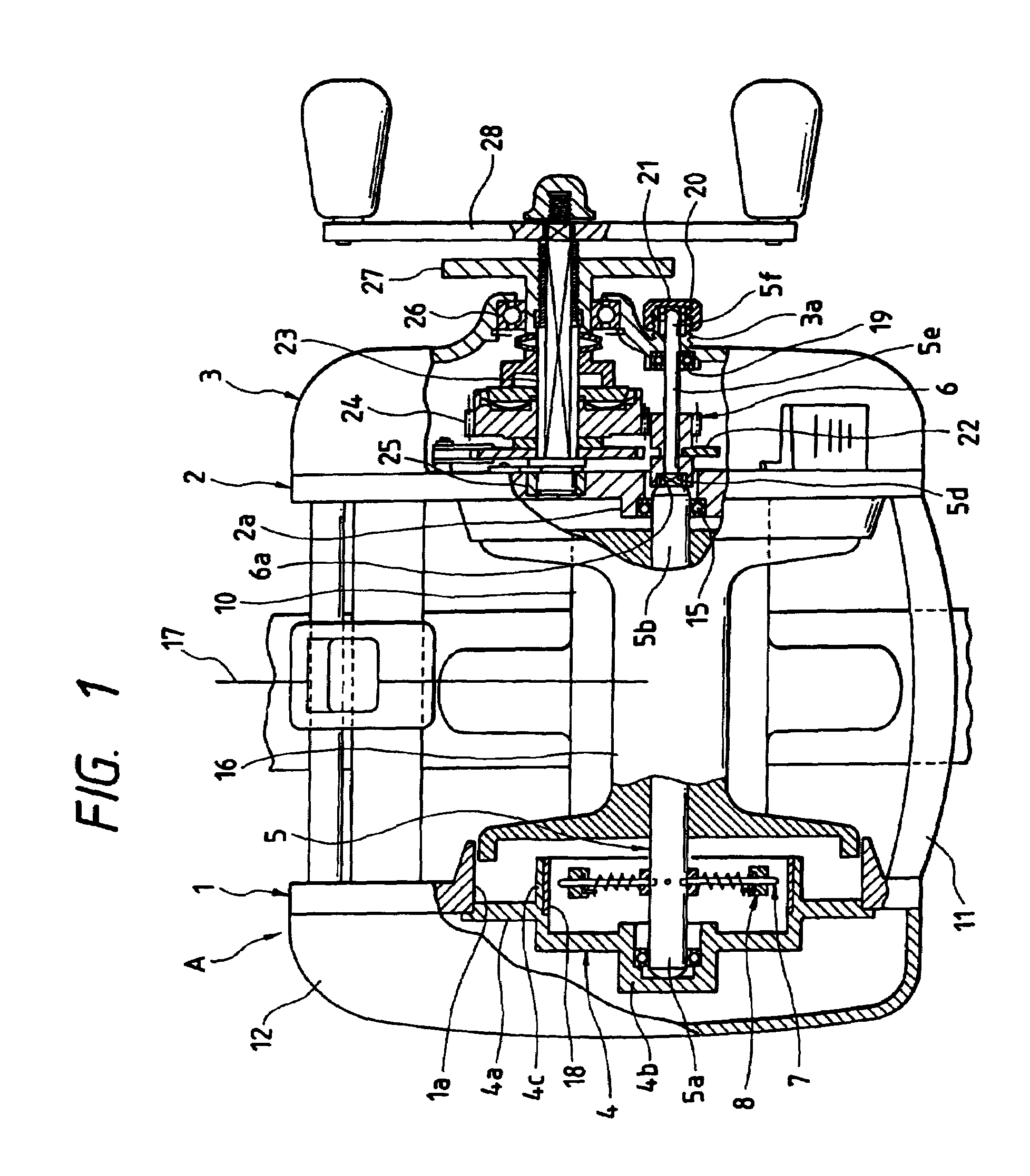
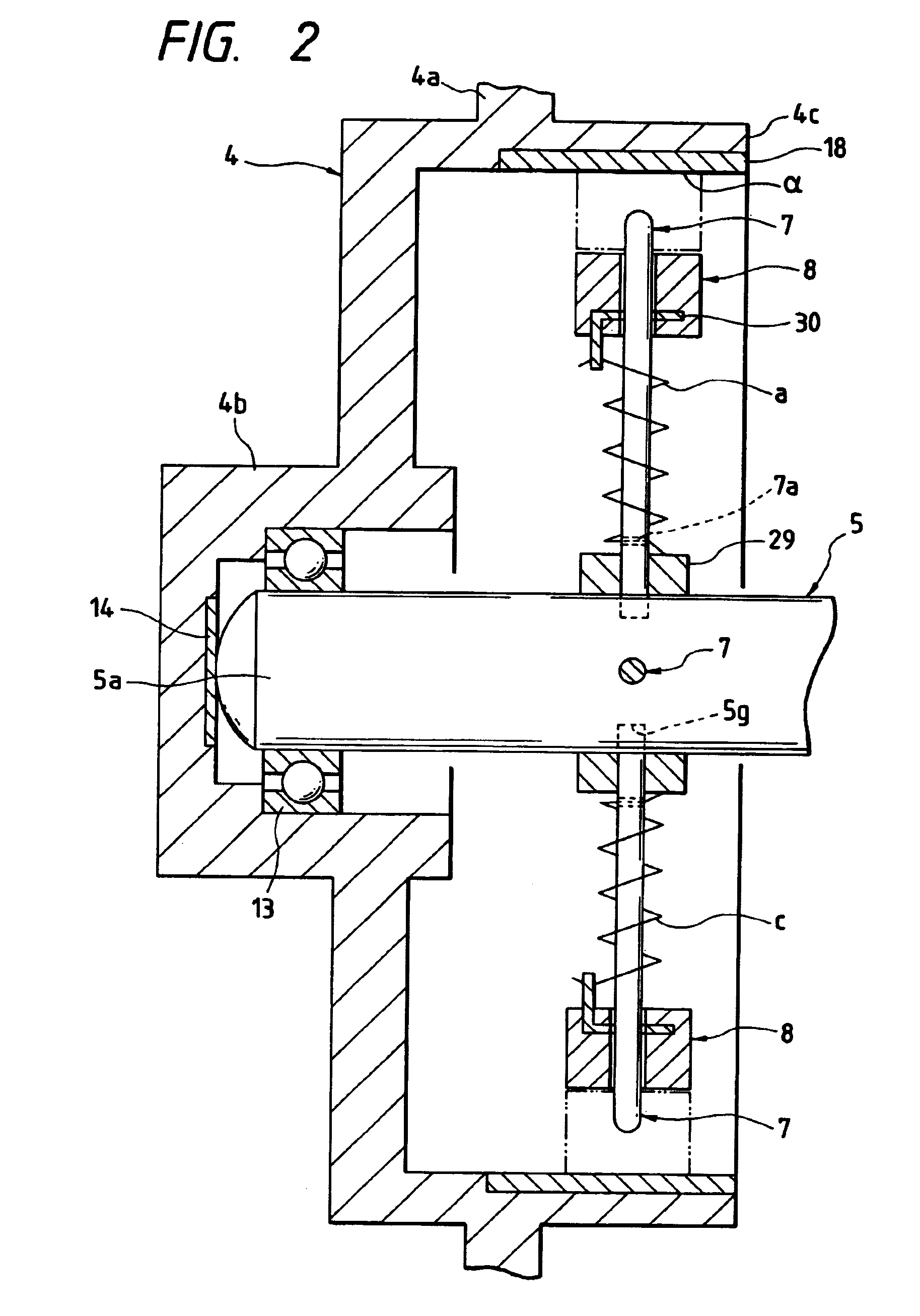
[0039]Now, description will be given below of a second embodiment of a fishing reel according to the invention with reference to the accompanying drawings. By the way, in the present embodiment, description will be given of a double-bearing type reel as a fishing reel. FIGS. 1 to 3 respectively show a first embodiment of the invention: in particular, FIG. 1 is a sectional plan view of the main portions of a fishing reel of a double-bearing type; FIG. 2 is an enlarged sectional plan view of the main portions of the left side of a fishing reel of a double-bearing type; and, FIG. 3 is an enlarged sectional plan view of the main portions of the left side of a fishing reel of a double-bearing type.

[0040]In FIG. 1, in a fishing reel of a double-bearing type, left and right side frames 1 and 2, which cooperate together in forming a reel main body A, are held in parallel to each other by a support column (not shown), a reel leg fixing plate 10 and a finger placement plate 11, while reel sid...

second embodiment

[0084]Now, description will be given below of a second embodiment of a fishing reel according to the invention with reference to the accompanying drawings. By the way, in the present embodiment, description will be given of a double-bearing type reel as a fishing reel.

[0085]As shown in FIG. 7, a double-bearing type reel 101 comprises a frame 102 including left and right frames 102a and 102b and a rod mounting portion (not shown) formed integrally with the central portions of the left and right frames 102a and 102b, and a reel main body 104 including left and right side plates 103a and 103b which are respectively mounted on the left and right frames 102a and 102b.

[0086]Between the left and right frames 102a and 102b (left and right side plates 103a and 103b), there is rotatably supported a spool shaft 106 through bearings 107a and 107b; and, on the spool shaft 106, there is mounted a spool 106a around which a fishing line can be wound.

[0087]The spool 106a is structured such that it ...

third embodiment

[0132]Now, description will be given below of a third embodiment of a fishing reel according to the invention. By the way, in the present embodiment, description will be also given of a double-bearing type reel as a fishing reel. In this third embodiment, the portions similar in structure to the second embodiment are given the same designation and thus the description thereof are omitted here.

[0133]As shown in FIGS. 12 to 13B, the centrifugal brake device 290 comprises a support member 292 fixed to the spool shaft 106 in a rotation preventive manner; an annular brake body 294 which is fixed to the reel main body 104 and also in the inner periphery of which there is formed a brake surface 294a; a plurality of brake members 296 which are respectively supported on the support member 292 in a removal preventive manner and can be moved not only in a direction where they approach the brake surface 294a of the annular brake body 294 but also in a direction where they are moved away from th...


PUM


Abstract

A fishing reel includes: a spool rotatably supported in a reel main body; a support member integrally rotating with the spool; a plurality of brake members slidably supported to the support member; and a brake surface provided in the reel main body, the brake surface being slidingly contactable with the brake members; wherein according to the rotation of the spool, an urging force is applied to the brake members in a direction where the brake members move away from the brake surface, and the brake members is slidingly contactable with the brake surface against the urging force, when a centrifugal force more than a predetermined value is applied to the spool.

Description

BACKGROUND OF THE INVENTION[0001]1. Field of the Invention[0002]The present invention relates to a fishing reel including a brake device capable of applying a brake force to a spool while the spool is rotating.[0003]2. Description of the Related Art[0004]In a casting operation, due to the weight of terminal tackles, reaction of a fishing rod, wind and the like, a spool can be rotated suddenly, so that the rotation speed of the spool can be faster than the play-out speed of a fishing line to thereby cause a backlash. The backlash raises some troubles: for example, the backlash can cause the different portions of the fishing line to be entwined together, or can cause the fishing line to be inserted into between the outer peripheral portion of the flange of the spool and the reel main body. To prevent such troubles, there is conventionally known a fishing reel which includes a centrifugal brake device.[0005]For example, in the registered Japanese Utility Model No. 2535505, Japanese Pat...

Claims


Application Information

Patent Timeline
Patent Type & Authority Patents(United States)
IPC IPC(8): A01K89/01A01K89/0155
CPCA01K89/0155A01K89/015A01K89/01557
Inventor MATSUZAWA, SHUICHIOISHI, HARUMICHIOTSU, TAKENORIEZUKA, NAOYUKI
Owner DAIWA SEIKO CORPORATION
Why Eureka
Try Eureka