Surveillance camera

a technology of surveillance camera and camera body, which is applied in the field of surveillance camera, can solve the problems of increased installation work, increased cost of surveillance device, and increased difficulty in surveillance in such a condition

Inactive Publication Date: 2008-01-03
SANYO ELECTRIC CO LTD
View PDF2 Cites 13 Cited by
  • Summary
  • Abstract
  • Description
  • Claims
  • Application Information

AI Technical Summary

Benefits of technology

[0010]When the surveillance camera 1 is to be mounted on a ceiling W1, the seating mount 21 of the base 2 is installed so as to be perpendicular to the axis of panning rotation L of the imaging lens 34. When the surveillance camera 1 is to be mounted on a wall W2, the seating mount 21 of the base 2

Problems solved by technology

Surveillance is difficult in such a condition.
However, when the above-explained conventional surveillance camera 1 is mounted on the wall W2, the cost there

Method used


Image

  • Surveillance camera
  • Surveillance camera
  • Surveillance camera

Examples


Embodiment Construction

[0022]Hereinafter, the preferred embodiment of the present invention will be described with reference to the accompanying drawings.

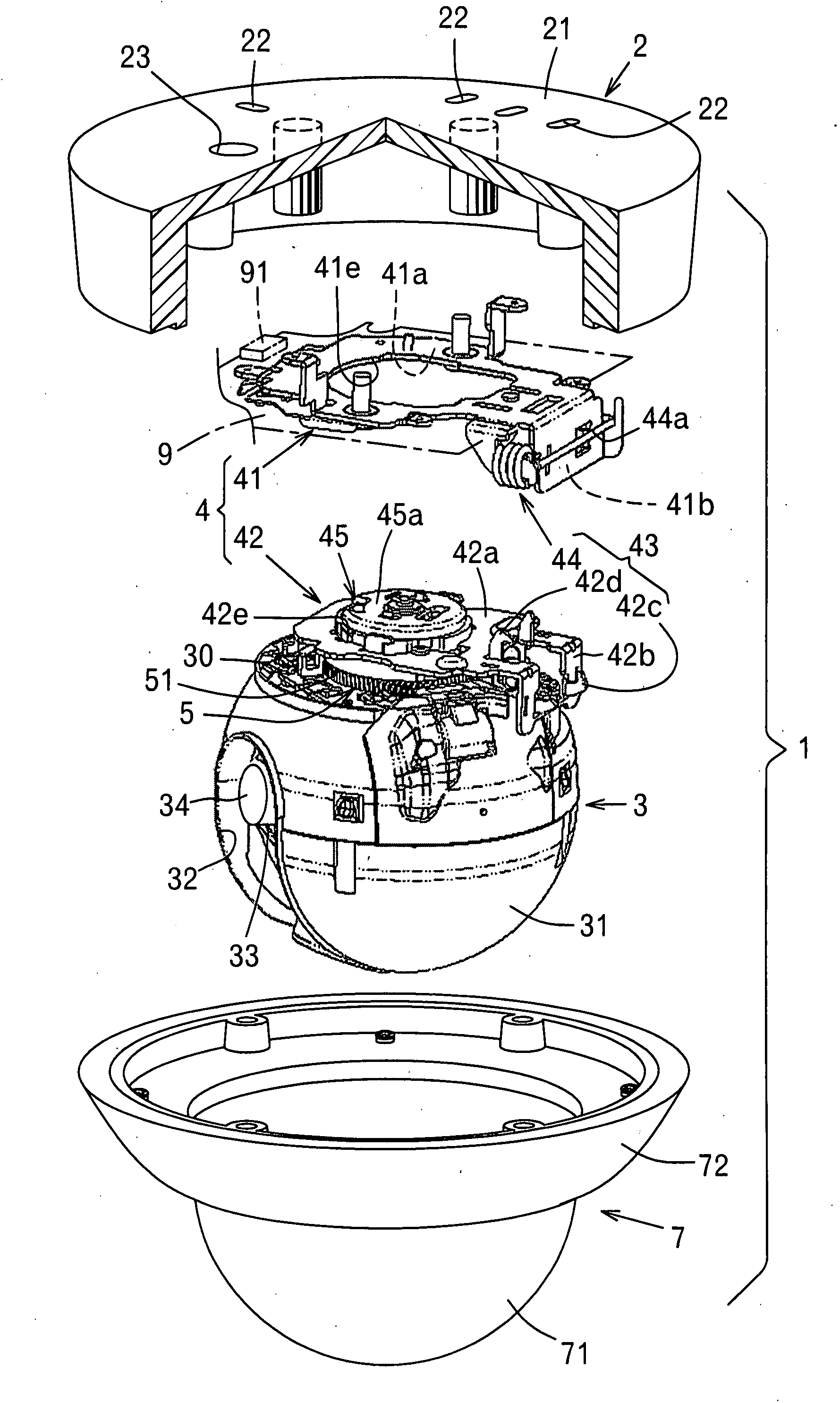
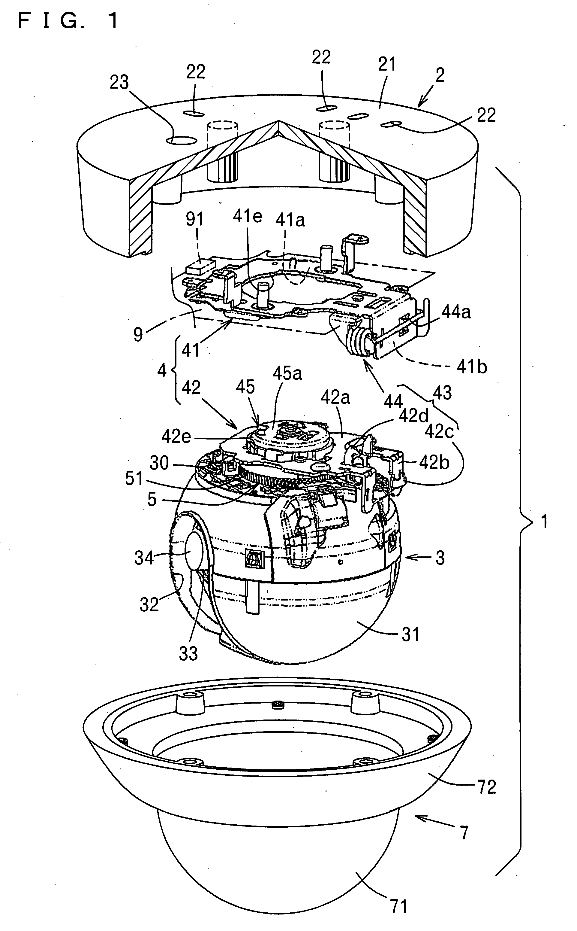
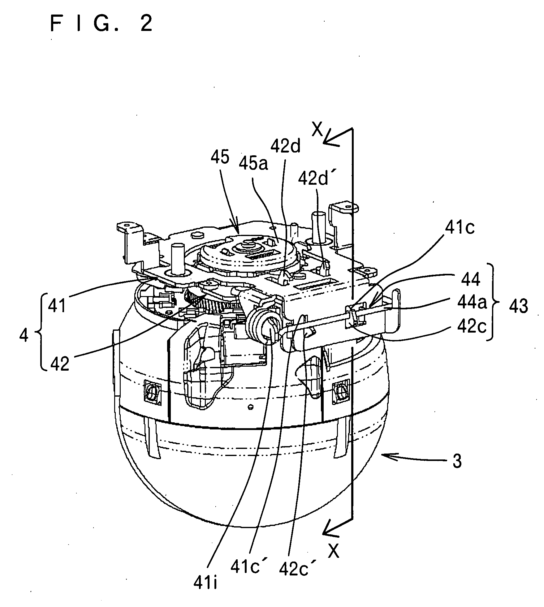
[0023]FIG. 1 is an exploded perspective view showing a dome-shaped surveillance camera 1 of this embodiment, and FIG. 2 is a perspective view of an imaging lens support member 3 and a switchable mounting unit 4, described hereinafter. Similar to a conventional surveillance camera, the surveillance camera 1 comprises a base 2, an imaging lens support member 3, a cover member 7, and a rotation drive device 5 rotating the imaging lens support member 3 in a panning direction. A switchable mounting unit 4 is disposed between the rotation drive device 5 and the base 2, and through an action of the switchable mounting unit 4, a mounting orientation of the imaging lens support member 3 with respect to the base 2 can be selectively changed by approximately 90 degrees.

[0024]The switchable mounting unit 4 is a characteristic of this embodiment, and schematic diagra...


PUM


Abstract

A surveillance camera comprises a base mounted on a wall, an imaging lens mounted on the base via an imaging lens support member and a switchable mounting unit, and a rotation drive device driving the imaging lens so as to rotate in a panning direction. The switchable mounting unit selects either a first posture wherein a seating mount of the base, making contact with the wall, is approximately perpendicular to an axis of panning rotation of the imaging lens or a second posture wherein the seating mount is approximately parallel to the axis of panning rotation, and mounts the imaging lens support member on the base.

Description

BACKGROUND OF THE INVENTION[0001]1. Field of the Invention[0002]The present invention relates to a surveillance camera. In particular, the present invention relates to a surveillance camera capable of correctly displaying the vertical positioning characteristics of a subject on a monitor, regardless of whether the surveillance camera is mounted on a ceiling or a wall.[0003]2. Description of the Related Art[0004]As shown in FIG. 7, a conventional dome-shaped surveillance camera 1 comprises a base 2, an imaging lens 34 supported on the base 2 via a lens support member 3 so as to be capable of rotating in a panning direction shown by Arrow A, a rotation drive device 5 driving the imaging lens 34 so as to rotate in the panning direction, and a controller (not shown) controlling a rotation range of the imaging lens 34. The imaging lens 34 is covered by a transparent cover member 7 and rotates not only in the panning direction of Arrow A but also in a tilting direction shown by Arrow F.[0...

Claims


Application Information

Patent Timeline
IPC IPC(8): H04N7/18
CPCH04N7/183
Inventor OKAMURA, SHIN-ICHIROLEE, JAEHYUN
Owner SANYO ELECTRIC CO LTD
Why Eureka
Try Eureka