Optoelectronic emitter mounted on a slider

a slider and optoelectronic technology, applied in the direction of maintaining the head carrier alignment, special recording techniques, instruments, etc., can solve the problems of hamr heads overheating the magnetic reading or writing components on the head, adversely affecting the control characteristics, and increasing the access time or unacceptably high electrical power consumption for position control

Inactive Publication Date: 2008-01-03
SEAGATE TECH LLC
View PDF39 Cites 110 Cited by
  • Summary
  • Abstract
  • Description
  • Claims
  • Application Information

AI Technical Summary

Problems solved by technology

There are conflicting design needs in improving performance of HAMR heads.
Various known solutions for coupling high levels of optical radiation to the HAMR head lead to arrangements that adversely affect control characteristics.
Increased mass and aerodynamic drag due to large optical source structures mounted on the HAMR head and / or head suspension and pivoting arm slow down movement of the HAMR head and lead to either increased access time or unacceptably high electrical power consumption for position control.
In addition, some optical source structures that are mounted to HAMR heads can overheat magnetic reading or writing components on the head.
When optical source structures are remotely mounted in a non-moving location, optical transmission media (such as lenses, mirrors or optical fibers) coupled between the optical source and the HAMR head add moving mass or a difficult-to-predict variable component of mechanical resistance to motion that leads to either increased access time or unacceptably high levels of electrical power consumption.

Method used


Image

  • Optoelectronic emitter mounted on a slider
  • Optoelectronic emitter mounted on a slider
  • Optoelectronic emitter mounted on a slider

Examples


Embodiment Construction

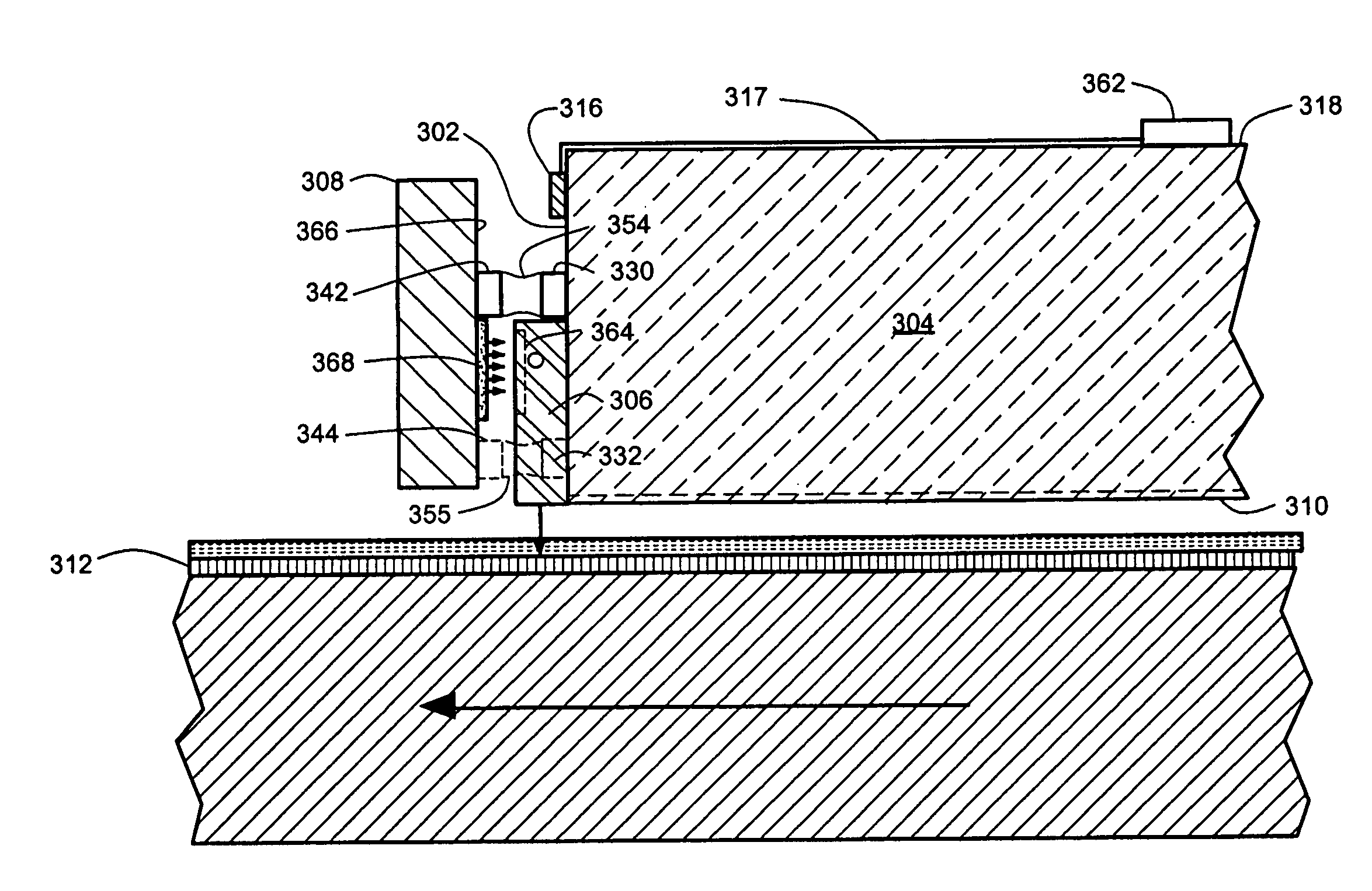
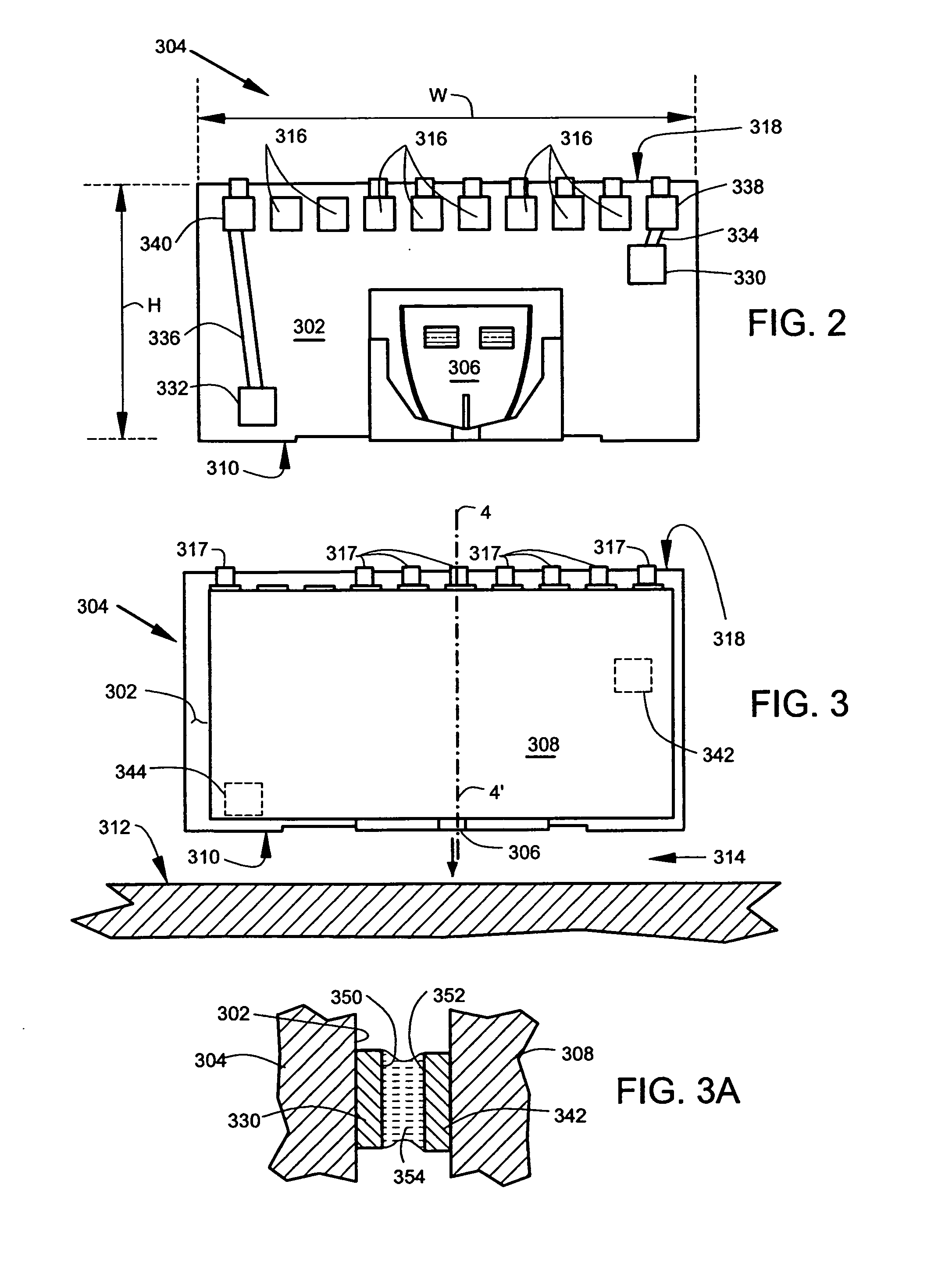
[0018]In the embodiments described below, an optoelectronic substrate is mounted to a trailing side of a slider using conductive bridges. The mounting aligns a optoelectronic emitter on the optoelectronic substrate with an optical input of a heat assisted magnetic recording head on the trailing side. In addition to providing alignment, the conductive bridge mounting serves as an electrical connections for supplying the optoelectronic emitter with electrical energization through conductors on the slider. The optoelectronic substrate is separated from the trailing side by a layer of air or gas that thermally insulates the recording head from heat produced on the optoelectronic substrate. Flex circuit connections are provided on a top surface of the slider, and no other electrical or optical connections to the optoelectronic substrate are needed. The arrangement provides a low mass source of radiation that does not inhibit dynamic motion of the slider.

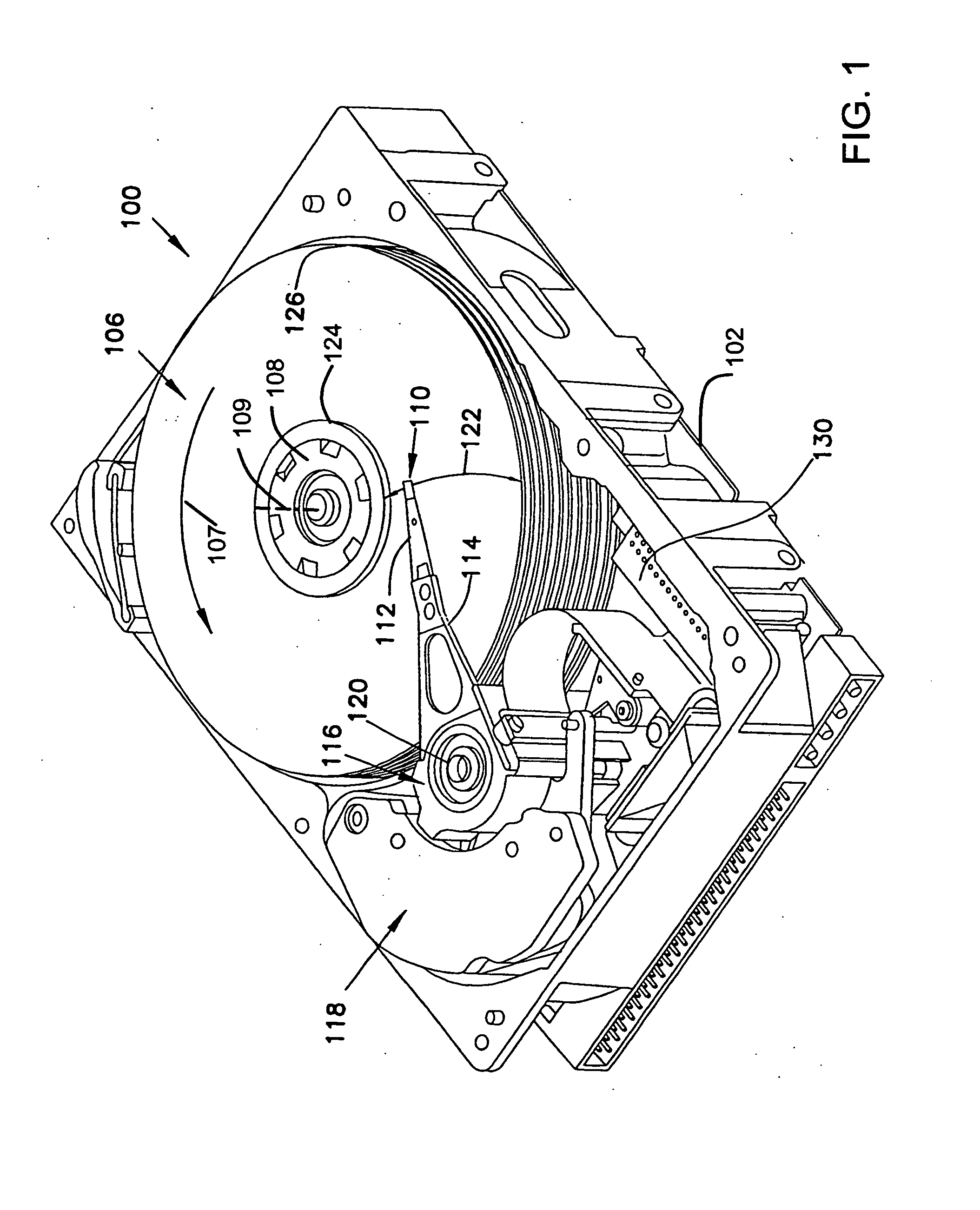
[0019]FIG. 1 illustrates an obliqu...


PUM

PropertyMeasurementUnit
heightaaaaaaaaaa
heightaaaaaaaaaa
diameteraaaaaaaaaa

Abstract

An apparatus comprising a slider including a slider substrate with a trailing side and a writer with bond pads disposed on the trailing side. The writer has an optic input for receiving an optic output. The apparatus comprises an optoelectronic substrate having a substrate surface facing the trailing side, and having contacts on the substrate surface that are joined to the bond pads by conductive bridges, and having an optoelectronic emitter adjacent the substrate surface for generating the optic output.

Description

FIELD OF THE INVENTION[0001]The present invention relates generally to data storage apparatus, and more particularly but not by limitation to heat assisted magnetic recording (HAMR) heads.BACKGROUND OF THE INVENTION[0002]There are conflicting design needs in improving performance of HAMR heads. There is a design need for a fast access time which requires enhanced control characteristics such as high speed, low overshoot positioning speed during seeking, and precise position controllability (during tracking) with a low expenditure of electrical power for position control in both modes. Enhanced control characteristics drive a design toward reducing moving mass and reducing mechanical and aerodynamic drag on the HAMR head and its suspension.[0003]There is a design need to deliver high levels of optical radiation to the HAMR head in order to provide rapid heating of magnetic media. Various known solutions for coupling high levels of optical radiation to the HAMR head lead to arrangemen...

Claims


Application Information

Patent Timeline
Patent Type & Authority Applications(United States)
IPC IPC(8): G11B5/60
CPCG11B5/314G11B2005/0021G11B2005/0005G11B5/59677
Inventor SLUZEWSKI, DAVID ALLEN
Owner SEAGATE TECH LLC
Why Eureka
Try Eureka