Image forming apparatus

a technology of image forming and forming sheets, which is applied in the direction of electrographic process apparatus, instruments, optics, etc., can solve the problems of uneven fixing, uniform axial nip width, and generation of recording material wrinkles, so as to reduce the number of output sheets per unit time

Inactive Publication Date: 2008-01-03
KONICA MINOLTA BUSINESS TECH INC
View PDF3 Cites 13 Cited by
  • Summary
  • Abstract
  • Description
  • Claims
  • Application Information

AI Technical Summary

Benefits of technology

[0012]The present invention has been made in view of such a problem, and the object of the present invention is to propose the image forming apparatus in which when the envelope is fixed, the wrinkle is not generated, and it is also not necessary that the number of output sheets per unit time is reduced.

Problems solved by technology

However, when the pressing force or the thickness of the elastic layer is increased, there is a case where the nip width in the axial direction becomes un-uniform, and there is a possibility that uneven fixing, or a wrinkle of recording material is generated.
Further, when the diameter of the roller is increased, there is a problem that not only a case where the size of the fixing apparatus is increased, but also a worming-up time is extended.
However, in the fixing apparatus written in Japanese Patent Publication Open to Public Inspection No. 10-228200, when the envelope is passed through, although the generation of the wrinkle can be prevented, when the contact-pressing force of the elastic pressing member is decreased, the fixing property is deteriorated.
In order to prevent the deterioration of the fixing property, it may be allowable when the conveyance speed of the envelope is decreased, however, the number of output sheets per unit time is decreased, and a problem that the productivity is decreased, is generated.

Method used


Image

  • Image forming apparatus
  • Image forming apparatus
  • Image forming apparatus

Examples


Embodiment Construction

[0020]Referring to the drawing, the embodiment relating to an image forming apparatus of the present invention will be described below.

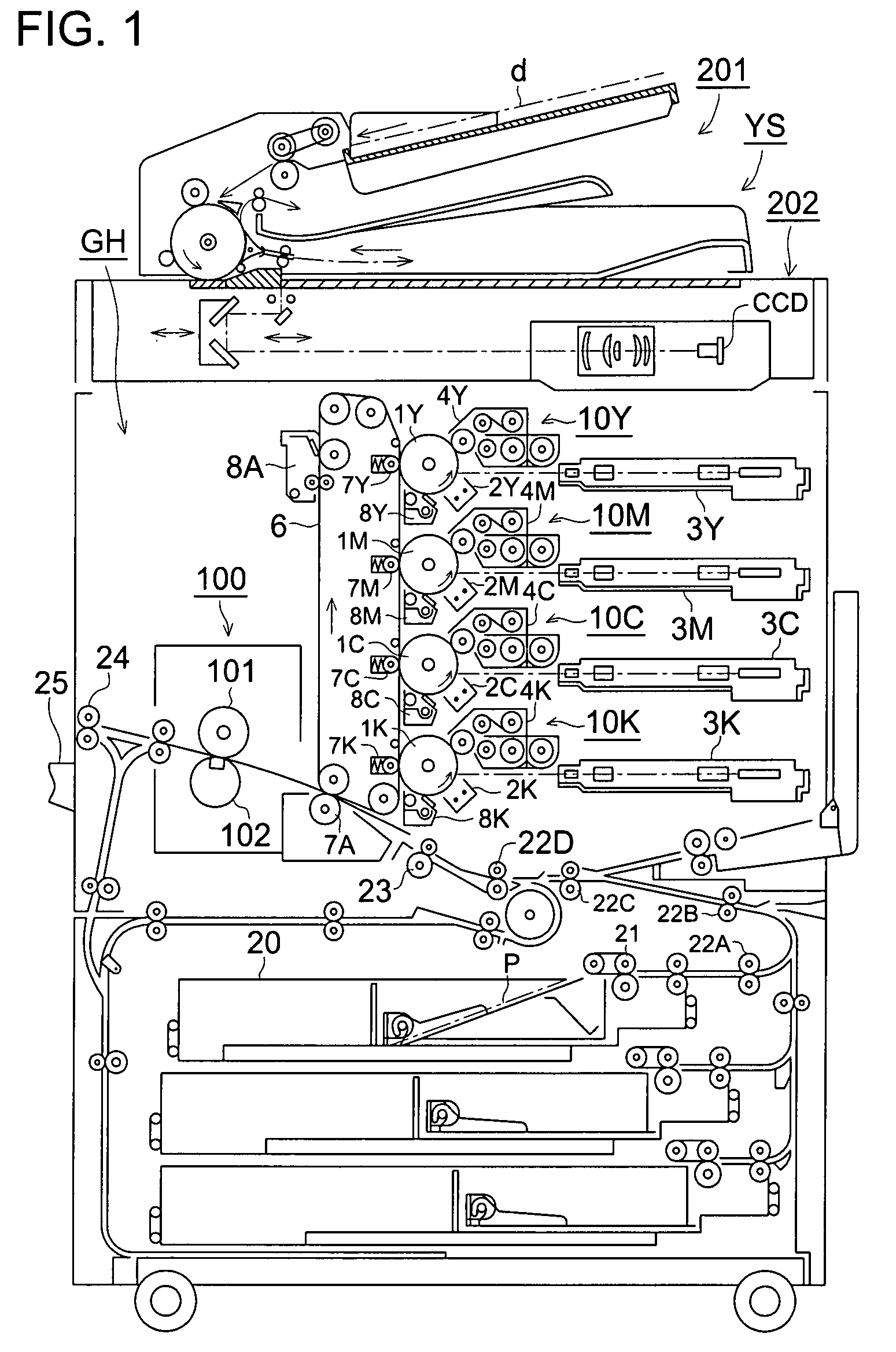
[0021]Initially, based on the structural view of FIG. 1, an example of the image forming apparatus will be described.

[0022]The present image forming apparatus is structured by the image forming apparatus main body GH and an image reading apparatus YS.

[0023]The image forming apparatus main body GH is called a tandem type color image forming apparatus, and structured by a plurality of sets of the image forming sections 10Y, 10M, 10C, 10K, a belt-like intermediate transfer body 6, feeding sheet passing sheet section and the fixing apparatus 9.

[0024]On the upper part of the image forming apparatus main body GH, the image reading apparatus YS composed of an automatic document feeding apparatus 201 and a document image scanning and exposing apparatus 202 is arranged. The document d placed on a platen of the automatic document feeding apparatus 201 is passe...


PUM


Abstract

An image forming apparatus comprising: a fixing roller; an endless fixing belt rotated together with the fixing roller; a pressurizing section arranged on the inner peripheral surface side of the fixing belt wherein the pressurizing section makes the fixing belt to be in pressure contact with the fixing roller, and corresponding to the outer peripheral surface of the fixing roller, the pressurizing section is deformed into concave-shape; a separation section which makes the fixing belt to be in pressure contact with the fixing roller, and by a tip of the separation section, the outer peripheral surface of the fixing roller is deformed into convex-shape, and a controller for controlling the pressing force of the separation section so that when an envelope is passed through as the recording material the pressing force becomes stronger than the pressing force when a plain paper passes through as the recording material.

Description

BACKGROUND OF THE INVENTION[0001]The present invention relates to a copier, printer, facsimile, and to a control of a fixing apparatus used for an electro-photographic type image forming apparatus such as a complex machine provided with these functions, and particularly, to a fixing apparatus for heating, pressuring and fixing a toner image formed in a recording material in a nip portion formed between a fixing roller and an endless fixing belt, and to an image forming apparatus provided with the fixing apparatus by which a wrinkle is not generated even when an envelope is passed through.[0002]In the electro photographic type image forming apparatus such as the complex machine provided with the copier, printer, facsimile, and these functions, a latent image corresponding to a document is formed on a photoreceptor drum and visualized when the toner is given to this latent image, and this visualized toner image is transferred onto the recording material, and after that, the toner imag...

Claims


Application Information

Patent Timeline
Patent Type & Authority Applications(United States)
IPC IPC(8): G03G15/20
CPCG03G2215/00514G03G15/6594G03G15/2032
Inventor TSUKAMURA, SHINICHIHORIE, TAKAYUKI
Owner KONICA MINOLTA BUSINESS TECH INC
Why Eureka
Try Eureka