Amoled display and driving method thereof

a technology of amoled display and driving method, which is applied in the direction of instruments, static indicating devices, etc., can solve the problems of increasing product costs, and achieve the effects of reducing production costs, reducing output channels, and facilitating operation

Active Publication Date: 2019-05-23
SHENZHEN CHINA STAR OPTOELECTRONICS SEMICON DISPLAY TECH CO LTD
View PDF2 Cites 5 Cited by
  • Summary
  • Abstract
  • Description
  • Claims
  • Application Information

AI Technical Summary

Benefits of technology

[0041]The present invention provides the following advantages: the invention provides an AMOLED display, wherein a display panel is provided with a plurality of multiplexers, each multiplexer has a multiplexer control end connected to receive a multiplexing control signal, a first input end electrically connected to the gate driver and a second input end to a constant low voltage. The first output end and the second output end are respectively connected to the first control end and the second control end of the corresponding rows of sub-pixel driving circuits. When the AMOLED display is driven, the multiplexer receives the scan signal from the gate driver, and under the control of the multiplex control signal, the first output end selectively outputs the scan signal or the constant low voltage, and the second output end selectively outputs the constant low voltage or the scan signal to generate two different control signals respectively outputted to the first control end and the second control end of the corresponding row of sub-pixel driving circuits. As such, the invention can effectively reduce the number of the output channels of the gate drivers to reduce the production cost. The invention also provides a driving method of AMOLED display, which is easy to operate and able to reduce the number of the output channels of the gate drivers to reduce the production cost.

Problems solved by technology

The number of the output channels of the gate driver 200′ is limited, which requires increasing the number of gate drivers 200′, resulting in increased product costs.

Method used


Image

  • Amoled display and driving method thereof
  • Amoled display and driving method thereof
  • Amoled display and driving method thereof

Examples


Embodiment Construction

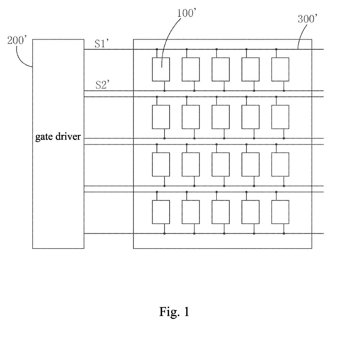
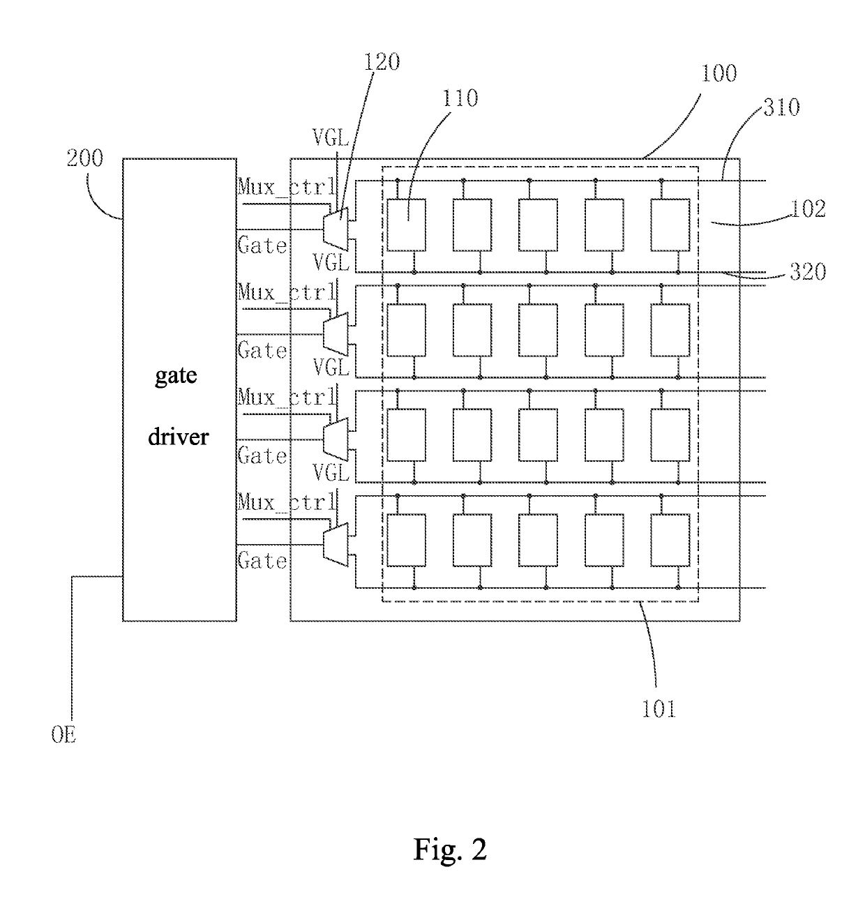
[0048]Referring to FIG. 2 and FIG. 3, the present invention provides an AMOLED display, which comprises: a display panel 100 and a gate driver 200 electrically connected to the display panel 100;

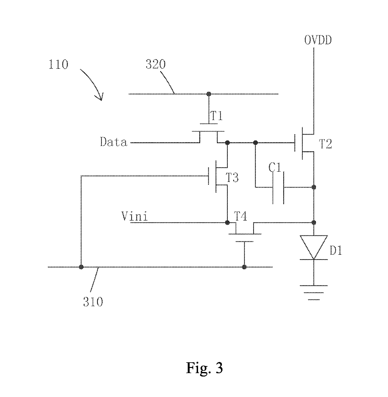
[0049]the display panel 100 comprising: a plurality of sub-pixel driving circuits 110 arranged in an array, and a plurality of multiplexers 120 corresponding to the plurality of rows of sub-pixel driving circuits 110; each multiplexer 120 having a control end connected to a multiplexing control signal Mux_ctrl, a first input end electrically connected to the gate driver 200, a second input end connected to a constant low voltage VGL, a first output end connected to a first control end corresponding to a row of sub-pixel driving circuits 110, and a second output connected to a second control end corresponding to a row of sub-pixel driving circuits 110.

[0050]Specifically, the AMOLED display disposes a first scan line 310 and a second scan line 320 corresponding to each row of sub-pixel driving...


PUM


Abstract

The invention provides an AMOLED display and driving method thereof, wherein a display panel is provided with a plurality of multiplexers, with each multiplexer having a multiplexer control end receiving a multiplexing control signal, a first input end connected to gate driver and a second input end to a constant low voltage. The first and second output ends are respectively connected to the first and second control ends of corresponding rows of sub-pixel driving circuits. When driving AMOLED display, the multiplexer receives scan signal from gate driver, and under control of multiplex control signal, the first and second output ends selectively output scan signal or the constant low voltage, respectively to generate two different control signals respectively outputted to the first and second control ends of corresponding row of sub-pixel driving circuits. The invention can reduce the number of the output channels of gate drivers to reduce production cost.

Description

BACKGROUND OF THE INVENTION1. Field of the Invention[0001]The present invention relates to the field of display techniques, and in particular to an active matrix organic light-emitting diode (AMOLED) display and driving method thereof.2. The Related Arts[0002]The organic light-emitting diode (OLED) display device provides the advantages of self-luminous, low driving voltage, high luminous efficiency, short response time, high definition and contrast, nearly 180° viewing angle, wide temperature range operation, ability to achieve flexibility display and large-area full-color display and many other advantages, and is thus recognized as the most promising display device in the industry.[0003]The OLED display can be classified into passive matrix OLED (PMOLED) and active matrix OLED (AMOLED) according to the driving mode, that is, the direct addressing and the thin film transistor (TFT) array addressing two categories. Among them, AMOLED has a pixel array, is an active display type, hig...

Claims


Application Information

Patent Timeline
Patent Type & Authority Applications(United States)
IPC IPC(8): G09G3/3266G09G3/3258
CPCG09G3/3266G09G3/3258G09G2310/0297G09G2310/061G09G2300/0426G09G3/3233G09G2300/0819G09G2300/0861G09G2310/0251G09G2310/0262G09G2320/043
Inventor WANG, LIMIN
Owner SHENZHEN CHINA STAR OPTOELECTRONICS SEMICON DISPLAY TECH CO LTD
Why Eureka
Try Eureka