
Touch display device

Inactive Publication Date: 2012-02-16
INNOLUX CORP
View PDF4 Cites 6 Cited by
  • Summary
  • Abstract
  • Description
  • Claims
  • Application Information

AI Technical Summary

Benefits of technology

[0007]Accordingly, the present invention has been made keeping in mind the above problems occurring in the prior art, and one aspect of the present invention is to provide a touch display device, which includes a digital logic circuit to significantly reduce the routing of the signal lines.
[0008]In one aspect of the present invention, by means of the digital logic circuit, the X-direction sensing lines and the Y-direction sensing lines in the touch display device are converted into signal lines in fewer amounts for outputting to the control chip. Due to the fewer amounts of the signal lines, not only the number of outputted signal lines can be reduced, but also the number of pins required in the control chip is decreased.

Problems solved by technology

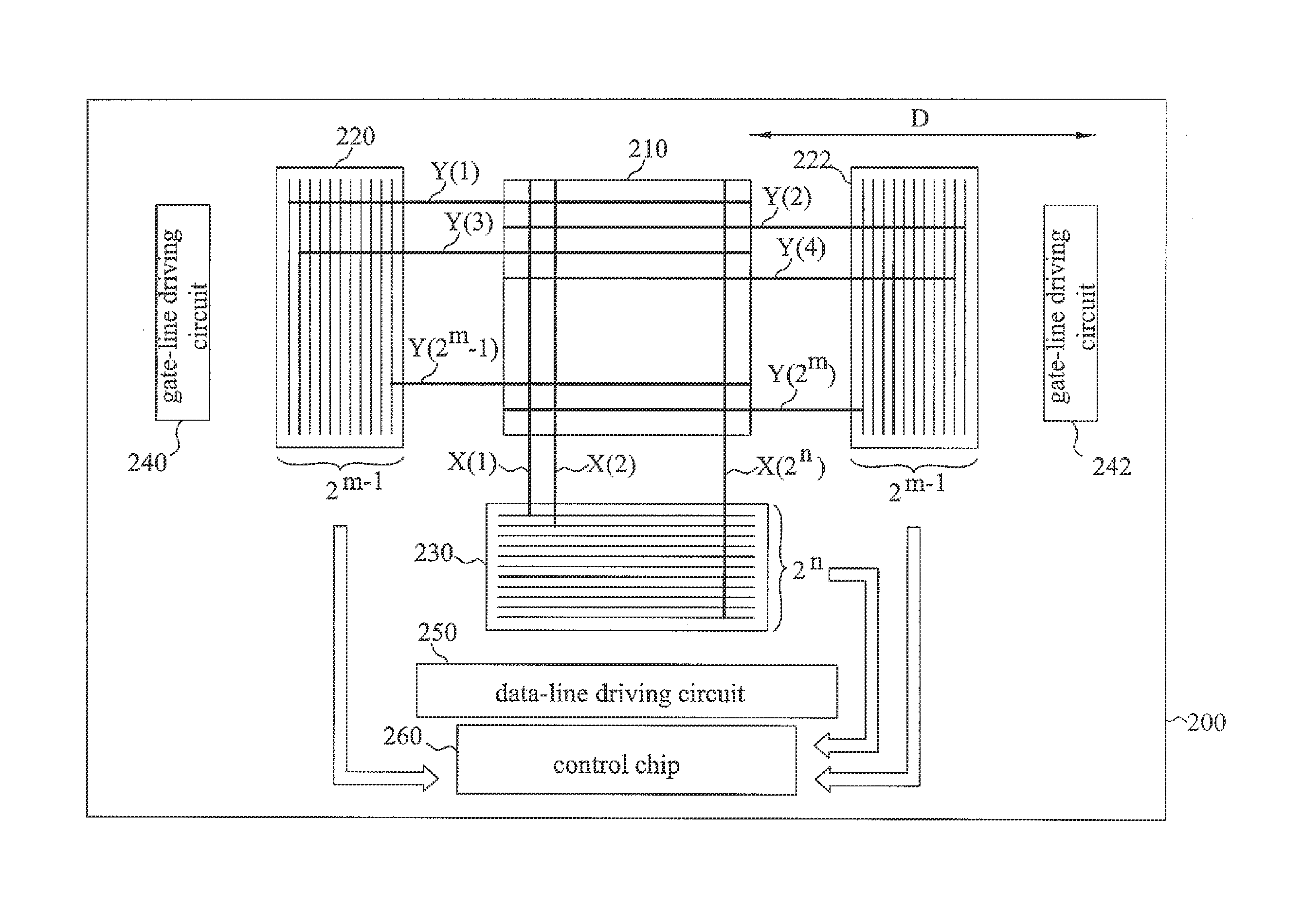
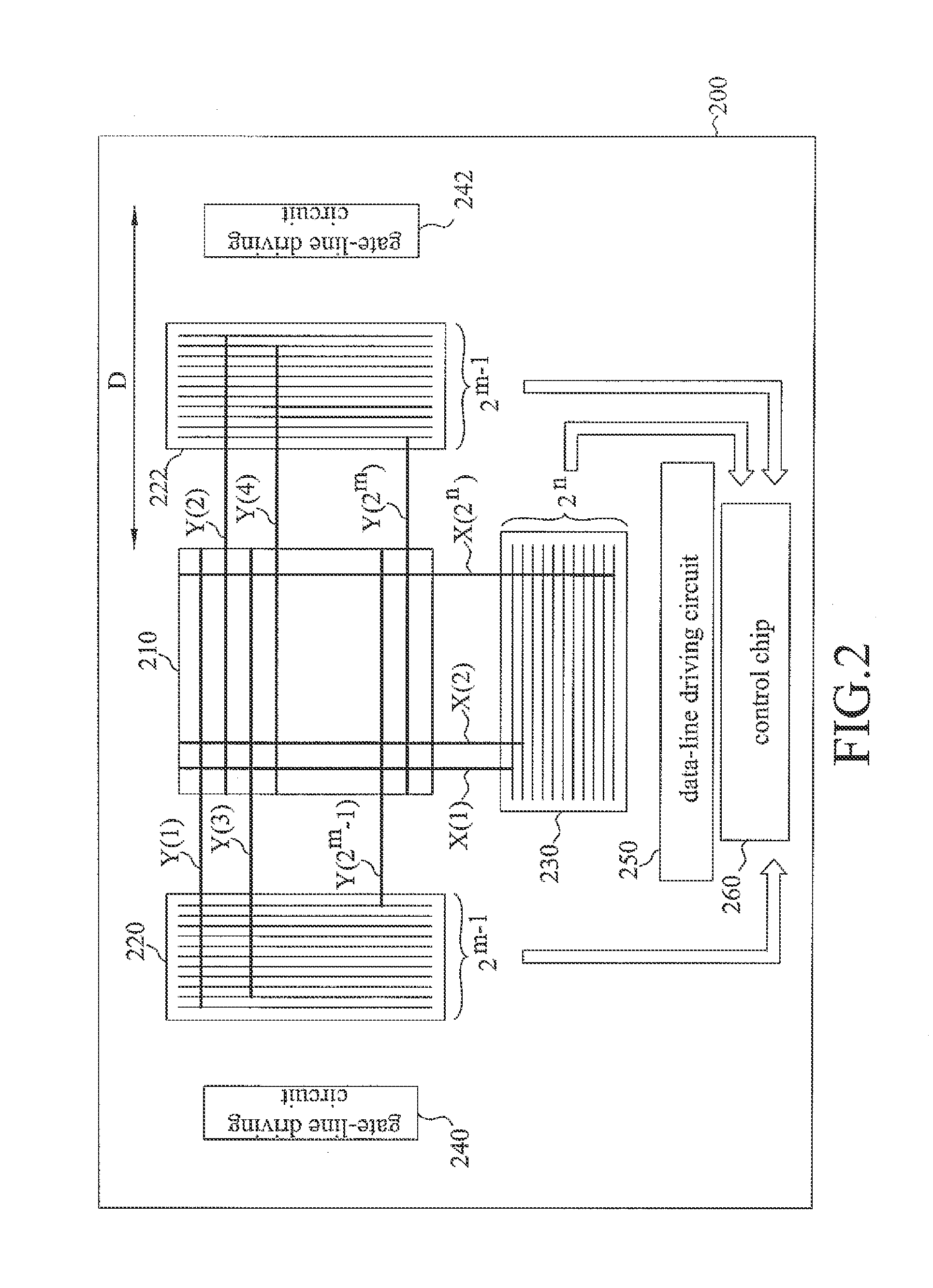
Such huge amount of sensing lines will result in overlarge frame width (D).

Method used


Image

  • Touch display device
  • Touch display device
  • Touch display device

Examples


Embodiment Construction

[0018]The present invention discloses a touch display device including at least one digital logic circuit for reducing the number of signal lines connected to the control chip to further reduce the frame width of the display device. The preferred embodiments of the present invention will now be described in greater details by referring to the following descriptions in reference with FIG. 3 through FIG. 5. The devices, elements, and processing steps described in the following embodiments are provided to illustrate the present invention and are not intended to be restrictive of the scope of the present invention.

[0019]FIG. 3 is a block diagram of a touch display device 300 in accordance with one embodiment of the present invention. The touch display device 300 includes a display panel 310, a vertical encoder 320, a horizontal encoder 330, a gate-line driving circuit 340, a data-line driving circuit 350, and a control chip 360.

[0020]The display panel 310 includes a plurality of pixel s...


PUM


Abstract

A touch display device is provided. The touch display device includes a display panel, a plurality of horizontal sensing lines, a plurality of vertical sensing lines, a horizontal encoder, a vertical encoder, and a control chip. The display panel includes a plurality of sensing elements arranged in matrix form, and the plurality of the horizontal sensing lines and the plurality of vertical sensing lines are connected with the plurality of the sensing elements, respectively. The horizontal encoder receives and encodes a plurality of horizontal sensing signals from the plurality of horizontal sensing lines and thereby forms a plurality of horizontal encoded signals whose number is less than that of the horizontal sensing signals. The vertical encoder receives and encodes a plurality of vertical sensing signals from the plurality of vertical sensing lines and thereby forms a plurality of vertical encoded signals whose number is less than that of the vertical sensing signals. The control chip receives and processes the horizontal encoded signals and the vertical encoded signals to obtain coordinates of a touch position on the display panel.

Description

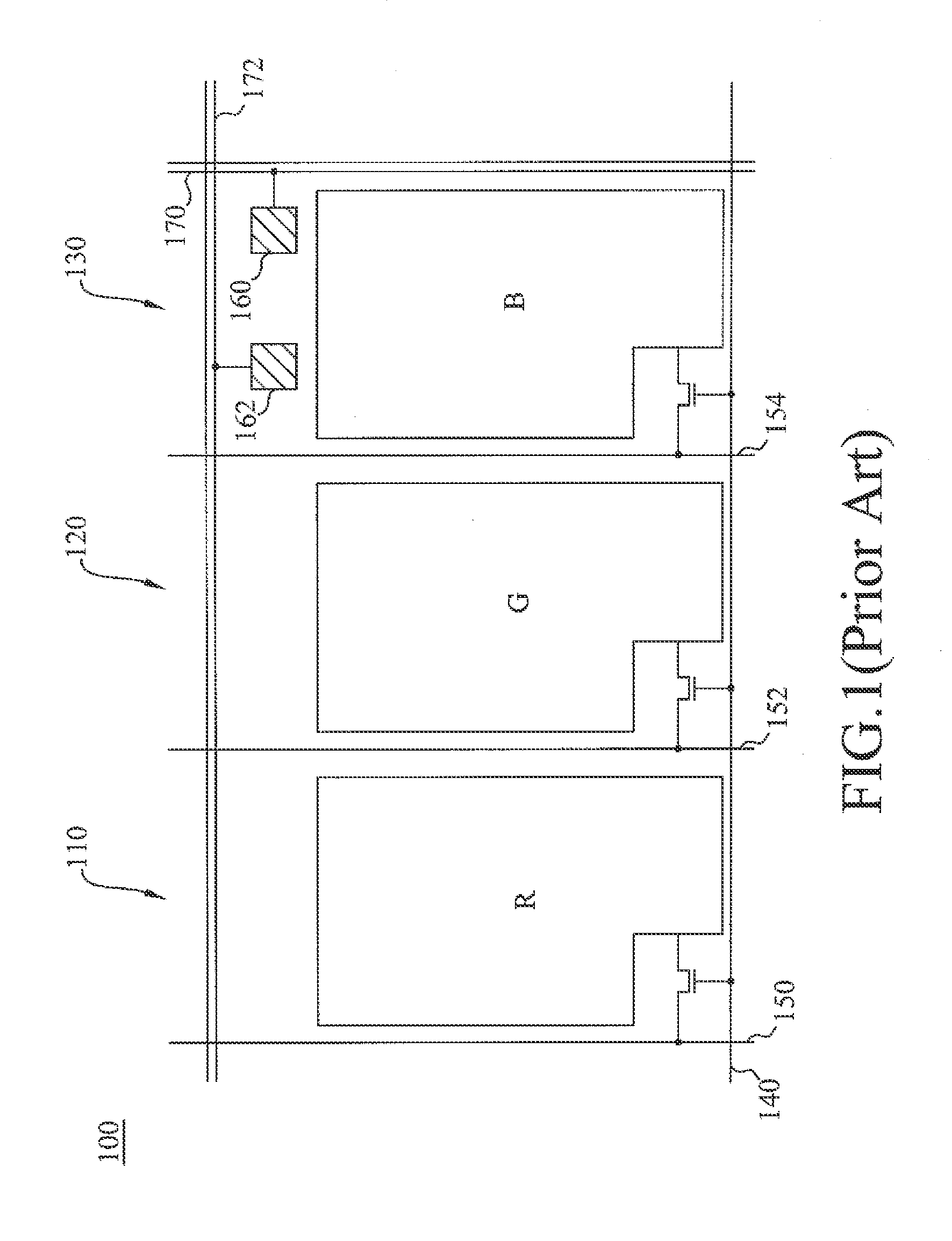
FIELD OF THE INVENTION[0001]The present invention relates to a touch display device, and more particularly to a touch display panel with reduced frame width.BACKGROUND OF THE INVENTION[0002]The use of touch display devices can not only conserve the space for deploying conventional mouse and keyboard, but also provide more user-friendly operations, therefore becoming one of the major interfaces of the electronic devices or machines. Currently, the in-cell touch technology integrating the touch sensing element into the pixel structure can provide better contrast and brightness than the conventional touch display device and thus receives more and more attentions.[0003]FIG. 1 illustrates the pixel structure 100 of a conventional touch display device, wherein the pixel structure 100 includes three sub-pixels: red (R), green (G), and blue (B). In general, each sub-pixel 110, 120, 130 includes a transistor and a pixel electrode and is driven by a gate line 140 and one of the three data lin...

Claims


Application Information

Patent Timeline
IPC IPC(8): G06F3/041
CPCG06F3/042G09G2310/0281
Inventor LIN, MENGYING
Owner INNOLUX CORP
Learn More