Advanced monitoring algorithm for regulated power systems with single output flag

a monitoring algorithm and output flag technology, applied in the direction of power supply lines, power conversion systems, instruments, etc., can solve the problems of increasing power consumption, reducing the size of the ics, and no longer good power provided on the output channel, so as to reduce the overall cost of the converter, reduce the amount of circuit area required within the converter, and reduce the cost of the converter

Active Publication Date: 2005-01-20
TEXAS INSTR INC
View PDF15 Cites 6 Cited by
  • Summary
  • Abstract
  • Description
  • Claims
  • Application Information

AI Technical Summary

Benefits of technology

[0012] By monitoring enabled output channels of the switch mode power converter while ignoring channels that have been disabled by a user, the power condition of the converter can be reported via a single output and the number of output pins required on the converter IC package can be r

Problems solved by technology

In recent years, the need for switch mode power supplies or DC-to-DC converters has risen dramatically as Integrated Circuits (ICs) such as Digital Signal Processors (DSPs) and mixed signal ICs have continued to decrease in size while their power consumption has increased.
Further, in the event the output voltage level falls outside the predetermined voltage range, the PGOOD signal may be asserted low by the converter, indicating that the power provided on the output channel is no longer good.
Although the above-described approach to monitoring output power levels of switch mode power converters has been successfully employed to monitor output power associated with a single channel within a converter, this approach frequently has drawbacks when used to monitor the output power associated with multiple converter channels.
However, using a separate PGOOD circuit for each channel within a switch m

Method used


Image

  • Advanced monitoring algorithm for regulated power systems with single output flag
  • Advanced monitoring algorithm for regulated power systems with single output flag
  • Advanced monitoring algorithm for regulated power systems with single output flag

Examples


Embodiment Construction

[0018] An improved method of monitoring the output power generated by a switch mode power converter is provided that reduces the overall cost of the converter. The presently disclosed output power monitoring technique lowers the cost of the converter by allowing the circuit area within the converter to be reduced while reducing the number of output pins on the converter IC package.

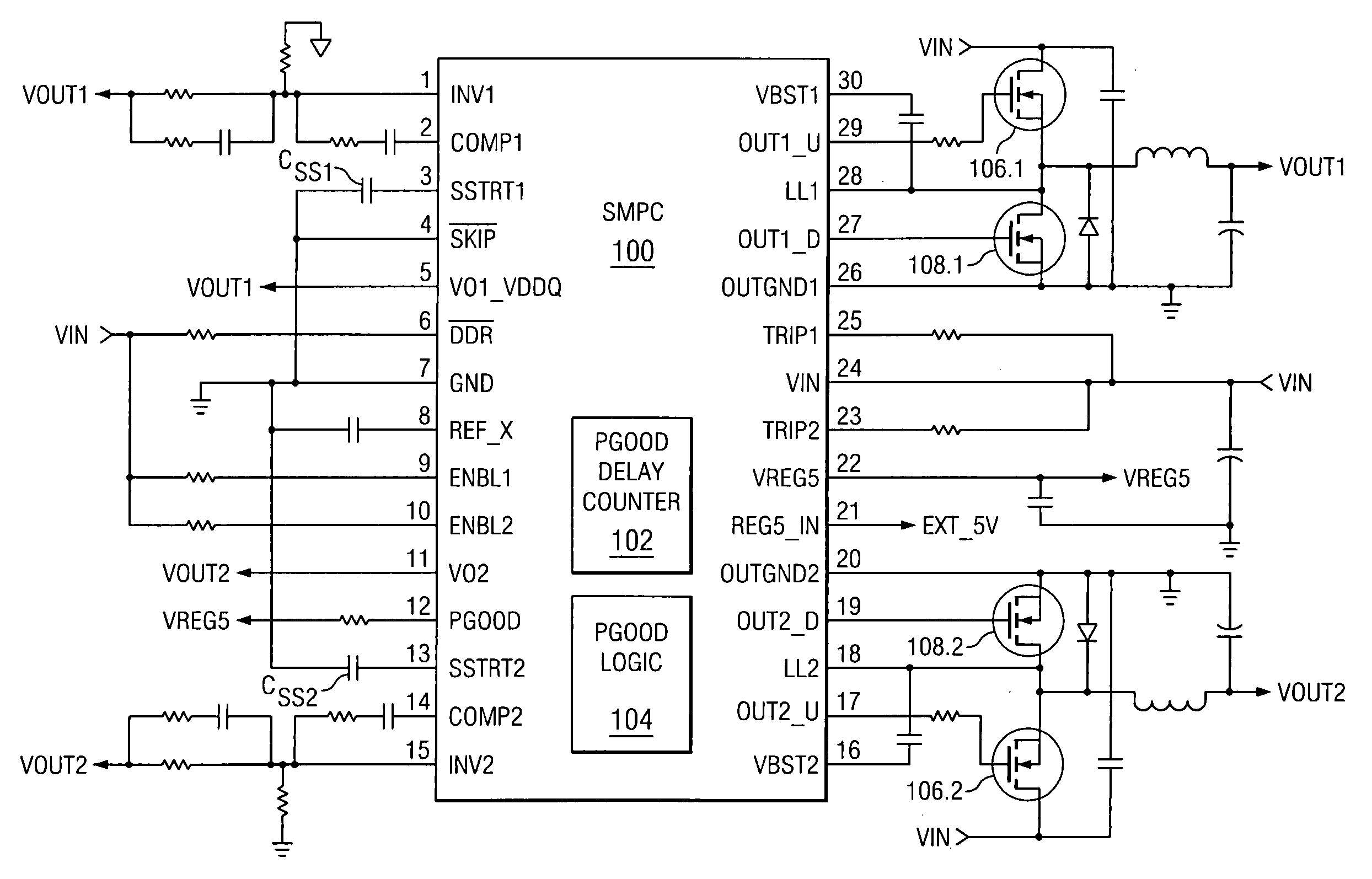
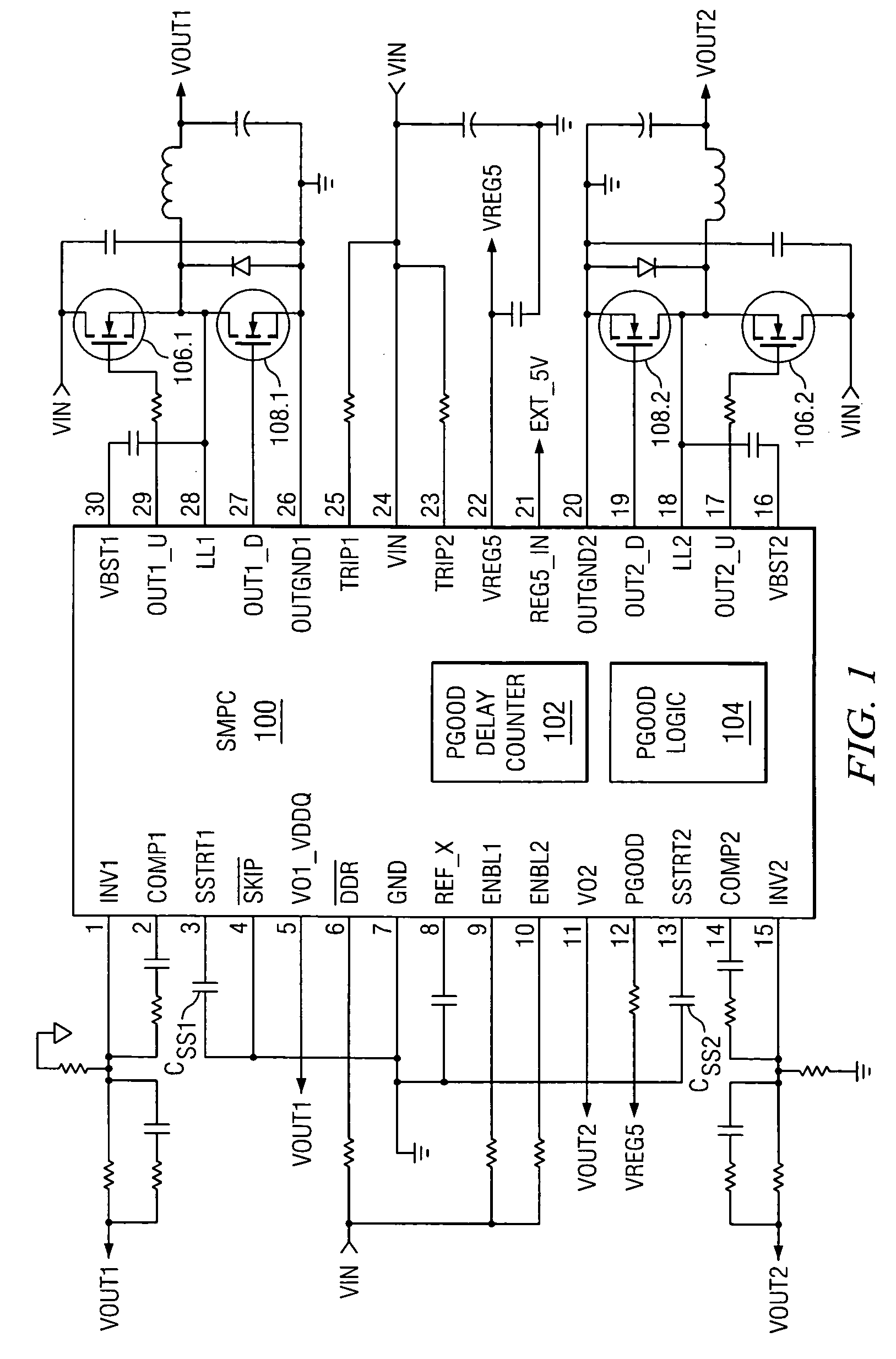
[0019]FIG. 1 depicts an illustrative embodiment of an application of a Switch Mode Power Converter (SMPC) 100, in accordance with the present invention. As shown in FIG. 1, the SMPC 100 includes dual voltage inputs VIN, dual sets of voltage outputs VOUT1-VOUT2, a single Power-Good (PGOOD) signal output, and enable inputs ENBL1-ENBL2 for enabling dual output channels 1-2, respectively, within the SMPC 100. Further, the SMPC 100 includes a PGOOD delay counter 102 and PGOOD logic circuitry 104 for implementing a method of monitoring the output power provided by the SMPC 100 on the channels 1-2.

[0020] In the...


PUM


Abstract

An improved method of monitoring the output power provided by a switch mode power converter that reduces the overall cost of the converter. The method includes initiating a soft-start procedure for a first output voltage in the event the first voltage channel is enabled. When the first voltage level comes within regulation, a delay counter counts a predetermined number of clock cycles. In the event a second output voltage channel is enabled between the time the first channel is enabled and the time the first voltage comes within regulation, a soft-start procedure is initiated for the second voltage and the delay counter re-starts when the second voltage comes within regulation. After the delay counter finishes counting, the first and second voltages are considered stable and a single Power-Good signal is asserted. In the event one of the channels is disabled by a user while the other channel remains enabled, the disabled channel is ignored and the PGOOD signal stays asserted to indicate that the power provided by the converter on the enabled channel is good.

Description

CROSS REFERENCE TO RELATED APPLICATIONS [0001] N / A STATEMENT REGARDING FEDERALLY SPONSORED RESEARCH OR DEVELOPMENT [0002] N / A BACKGROUND OF THE INVENTION [0003] The present application relates generally to switch mode power supplies, and more specifically to switch mode power converters capable of generating Power-Good signals indicative of whether power corresponding to one or more output voltage channels of the converter is within a predetermined acceptable range. [0004] In recent years, the need for switch mode power supplies or DC-to-DC converters has risen dramatically as Integrated Circuits (ICs) such as Digital Signal Processors (DSPs) and mixed signal ICs have continued to decrease in size while their power consumption has increased. Switch mode power converters are typically employed in such ICs for converting positive or negative input supply voltages to output supply voltage levels that are appropriate for powering circuitry within the IC and / or for powering circuitry ext...

Claims


Application Information

Patent Timeline
IPC IPC(8): H02M1/00H02M1/36
CPCH02M1/36Y10S323/901H02M2001/008H02M1/008
Inventor NI, CHUANSANZO, CHRISTOPHER J.SHERMAN, TODD M.
Owner TEXAS INSTR INC
Why Eureka
Try Eureka