Thermal printer and printing device

Active Publication Date: 2008-01-03
TOSHIBA TEC KK +1
View PDF14 Cites 19 Cited by
  • Summary
  • Abstract
  • Description
  • Claims
  • Application Information

AI Technical Summary

Benefits of technology

[0024]According to this configuration, head loads of the first and second printing heads on

Problems solved by technology

Thus, a space must be provided to receive the coil spring in the cover, which has caused enlargement of the thermal printer.
The following problem has occurred in the above thermal printer.
Consequently, when the cap is opened/closed, the platen interferes with the casing side.
Thus, a complex operation of opening/closing the opening/closing cap after shifting it in a direction away from the thermal head, or the like is necessary.
However, in the thermal printer of this configuration, as the thermal printer is pressed to the platen roller in the closed state to

Method used


Image

  • Thermal printer and printing device
  • Thermal printer and printing device
  • Thermal printer and printing device

Examples


first embodiment

[0045]A first embodiment of the present invention will be described below with reference to the accompanying drawings.

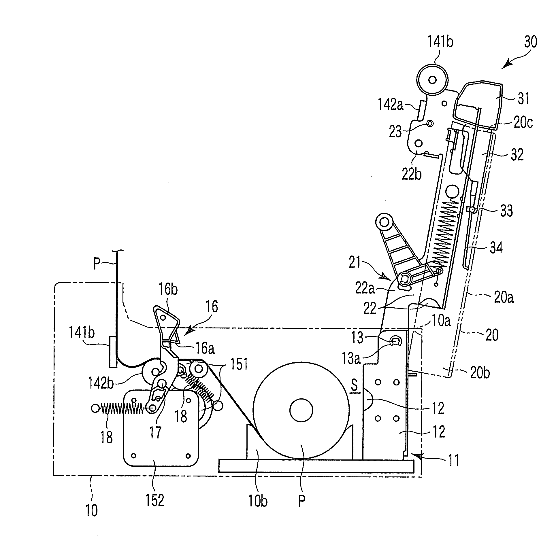
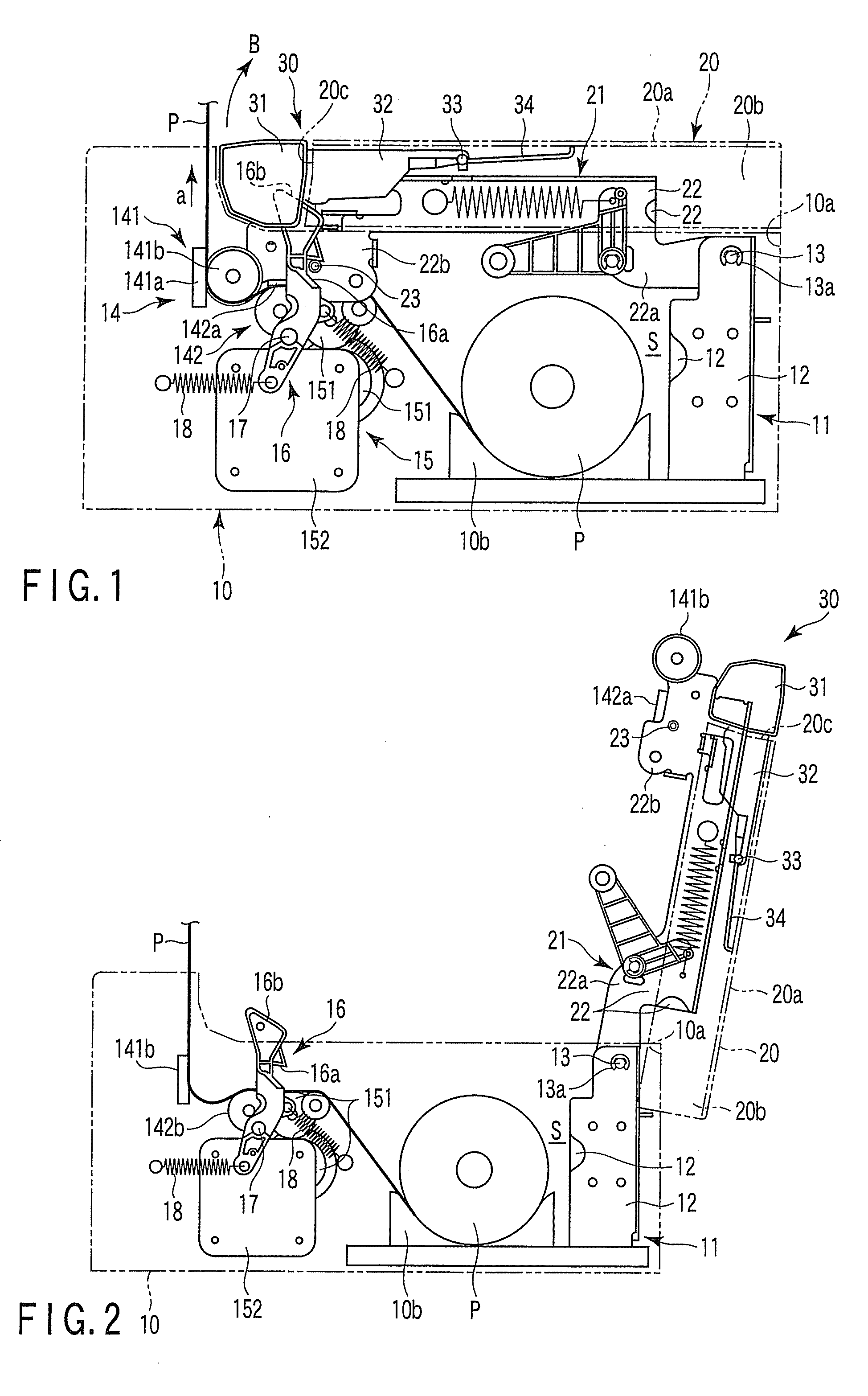
[0046]FIG. 1 is a schematic diagram of a thermal printer when a cover 20 is closed according to the first embodiment of the present invention, and FIG. 2 is a schematic diagram of the thermal printer when the cover is opened according to the embodiment. For example, the thermal printer of the embodiment is mounted on a register or the like to be used for printing a receipt. As shown in FIGS. 1 and 2, such a thermal printer includes a housing 10 as a main body casing, and a cover 20 for opening / closing an opening 10a of the housing 10.

[0047]The housing 10 has a rectangular box shape, and a housing frame 11 is arranged therein. The housing frame 11 includes two frame bodies 12 arranged on both sides of the housing 10, and a reception space (space) S is formed nearby to receive thermosensitvie paper P. The thermosensitive paper P is wound in a roll to be placed on a bas...

second embodiment

[0080]FIG. 7 is a longitudinal sectional diagram schematically showing a thermal printer 210 according to a second embodiment of the present invention, FIG. 8 is a longitudinal sectional diagram showing a main section of an opening / closing cap of the thermal printer 210, FIG. 9 is a longitudinal sectional diagram showing the main section of the opening / closing cap of the thermal printer 210, and FIG. 10 is a longitudinal diagram schematically showing a state in which the opening / closing cap of the thermal printer 210 is opened. In the drawings, P denotes thermosensitive paper. In each of FIGS. 7 to 10, a left side is equivalent to one side of a casing main body 220, and a right side is equivalent to the other side of the casing main body 220.

[0081]The thermal printer 210 includes the casing main body 220 for housing each mechanism, and an opening / closing mechanism 230 disposed to be opened / closed with respect to the casing main body 220.

[0082]The casing main body 220 includes a base...

third embodiment

[0097]A thermal printer 310 according to a third embodiment of the present invention will be described below by referring to FIGS. 12 to 15.

[0098]FIG. 12 schematically shows the inside of the thermal printer 310. This thermal printer 310 has a function of printing in a thermal sheet 311, and it can be used for, for example, a cash register or the like.

[0099]The thermal printer 310 includes a printer main body 312 having its upper part opened, and a cover 314 to cover this opening. The cover 314 is fixed to a hinge part 312 formed in an upper part of the printer main body 312 to rotate and to be opened / closed.

[0100]The hinge part 315 includes a twist spring 316 disposed as an urging member. One end of the twist spring 316 abuts the printer main body 312, and the other end abuts the cover 314. The cover 314 is urged to the printer main body 312 in an opening direction by this twist spring 316.

[0101]An engaging pin 319 is disposed on the side of the cover 314. The engaging pin 319 is f...


PUM


Abstract

According to an aspect of the present invention, a thermal printer includes a housing in which a space is formed, printing means disposed in the housing, a cover disposed in the housing and which comes into contact with and separates from the housing when rotated, thereby opening and closing the space, urging means for urging the cover in a direction away from the housing, an engaging part which is disposed in the housing and which prevents the movement of the cover in a direction away from the housing when engaged with the cover, a pressed part which is disposed rotatably in the cover and which moves the engaging part when pressed, thereby releasing engagement between the cover and the engaging part, and elastic means arranged to urge the pressed part in a direction away from the engaging part.

Description

CROSS-REFERENCE TO RELATED APPLICATIONS[0001]This application is based upon and claims the benefit of priority from prior Japanese Patent Applications No. 2006-178944, filed Jun. 29, 2006; No. 2006-178948, filed Jun. 29, 2006; No. 2006-178957, filed Jun. 29, 2006; No. 2006-188502, filed Jul. 7, 2006; and No. 2007-014112, filed Jan. 24, 2007, the entire contents of all of which are incorporated herein by reference.BACKGROUND OF THE INVENTION[0002]1. Field of the Invention[0003]The present invention relates to a thermal printer mounted on, e.g., a register, and a printing device.[0004]2. Description of the Related Art[0005]There has been known a thermal printer mounted on, e.g., a register or the like, to print various pieces of information in a receipt made of thermosensitive paper. Normally, for example, as described in Jpn. Pat. Appln. KOKAI Publication No. 11-286147, the thermal printer includes a thermal head for heating the thermosensitive paper and a platen roller for pressing ...

Claims


Application Information

Patent Timeline
IPC IPC(8): B41J3/60B41J29/00
CPCB41J3/60B41J29/02B41J15/042
Inventor SEKINO, TOSHIHARUTAKAHASHI, KOUSUKEHIYOSHI, TAKESHINIHASHI, KIYOTAKASANADA, TSUYOSHI
Owner TOSHIBA TEC KK
Why Eureka
Try Eureka