Method for detecting an error in the opening behavior of an injector

a technology of injector and opening behavior, which is applied in the direction of machines/engines, electrical control, instruments, etc., can solve the problems of delay periods, unblocking of fuel flow, and blocking of fuel flow in injectors

Inactive Publication Date: 2015-05-07
ROBERT BOSCH GMBH
View PDF11 Cites 12 Cited by
  • Summary
  • Abstract
  • Description
  • Claims
  • Application Information

AI Technical Summary

Benefits of technology

[0017]The method according to the present invention may, in this case, be carried out during the regular operation of the internal combustion engine, since the ballistic partial injection may be advantageously carried out in a quantity and torque neutral manner. The present invention is to be carried out simply and with little effort. There is no need for carrying out retrofitting measures at the internal combustion engine. Thus, an on-board diagnosis may be implemented in which it is monitored during the regular operation of the internal combustion engine whether an error is present in the opening behavior of the injector. In this way, the individual injectors of an internal combustion engine may be monitored in a simple manner. A defective injector having an error in the opening behavior may thus be detected early and replaced. In particular, a corresponding measure may be carried out when an error in the opening behavior is detected.
[0021]The injector may be, in particular, configured as a magnetic injector or as a piezoelectric injector. In this case, the valve element of a magnetic injector has, in particular, an armature or a magnet armature. In the course of the ballistic partial injection, a coil of the magnetic injector is activated for a comparably short period of time. Before the armature reaches a lift stop and before the magnetic injector is fully opened, the armature and the valve needle move in the opposite direction and the magnetic injector re-closes. The valve element of a piezoelectric injector has, in particular, a piezoelectric actuator. In this case, this piezoelectric actuator is activated for a comparably short period of time in the course of the ballistic partial injection.
[0025]A diagnosis of the injector may be carried out if an error in the opening behavior is detected. It is checked in this case whether an error is in fact present in the opening behavior. In the course of this diagnosis, the injector is thoroughly examined and the opening behavior of the injector is precisely determined. A diagnosis of this type is carried out, in particular, outside of the regular operation of the internal combustion engine. For this purpose, the internal combustion engine is, in particular, operated in a special mode. In the course of this special mode, a basic adaption of the internal combustion engine is carried out, in particular. Here, test runs and learning injections are carried out, in particular, and the internal combustion engine is operated according to certain fuel pressure specifications. In this way, the result of the method according to the present invention may be initially verified prior to replacing the injector. Thus, the result of the method according to the present invention is cross-checked one more time, thus preventing a non-defective injector from being erroneously replaced.
[0027]The ballistic partial injection may be carried out in a quantity and torque neutral manner. In this way, the ballistic partial injection does not influence or exacerbate the smooth running, the fuel consumption, the exhaust gas values or the performance output of the internal combustion engine. In particular, when the ballistic partial injection is carried out prior to a stroke in the course of the full stroke injection, the ballistic partial injection still does not influence the internal combustion engine.

Problems solved by technology

This, in turn, results in that in the case of an NC injector, the flow of the fuel is unblocked or, in the case of an NO injector, the flow of the fuel is blocked.
During this process, delay periods occur in injectors.
An error of this type in the opening behavior means in most cases a change in the opening delay period due to wear and tear of the injector, for example.
Errors which, for example, result in increased fuel consumption and increased emissions of the internal combustion engine should be detected early on.
Determining the opening delay period according to DE 10 2009 028 650 A1, for example, is, however, very complex and requires a lot of effort, and cannot be readily implemented in the ongoing operation of an internal combustion engine.

Method used


Image

  • Method for detecting an error in the opening behavior of an injector
  • Method for detecting an error in the opening behavior of an injector
  • Method for detecting an error in the opening behavior of an injector

Examples


Embodiment Construction

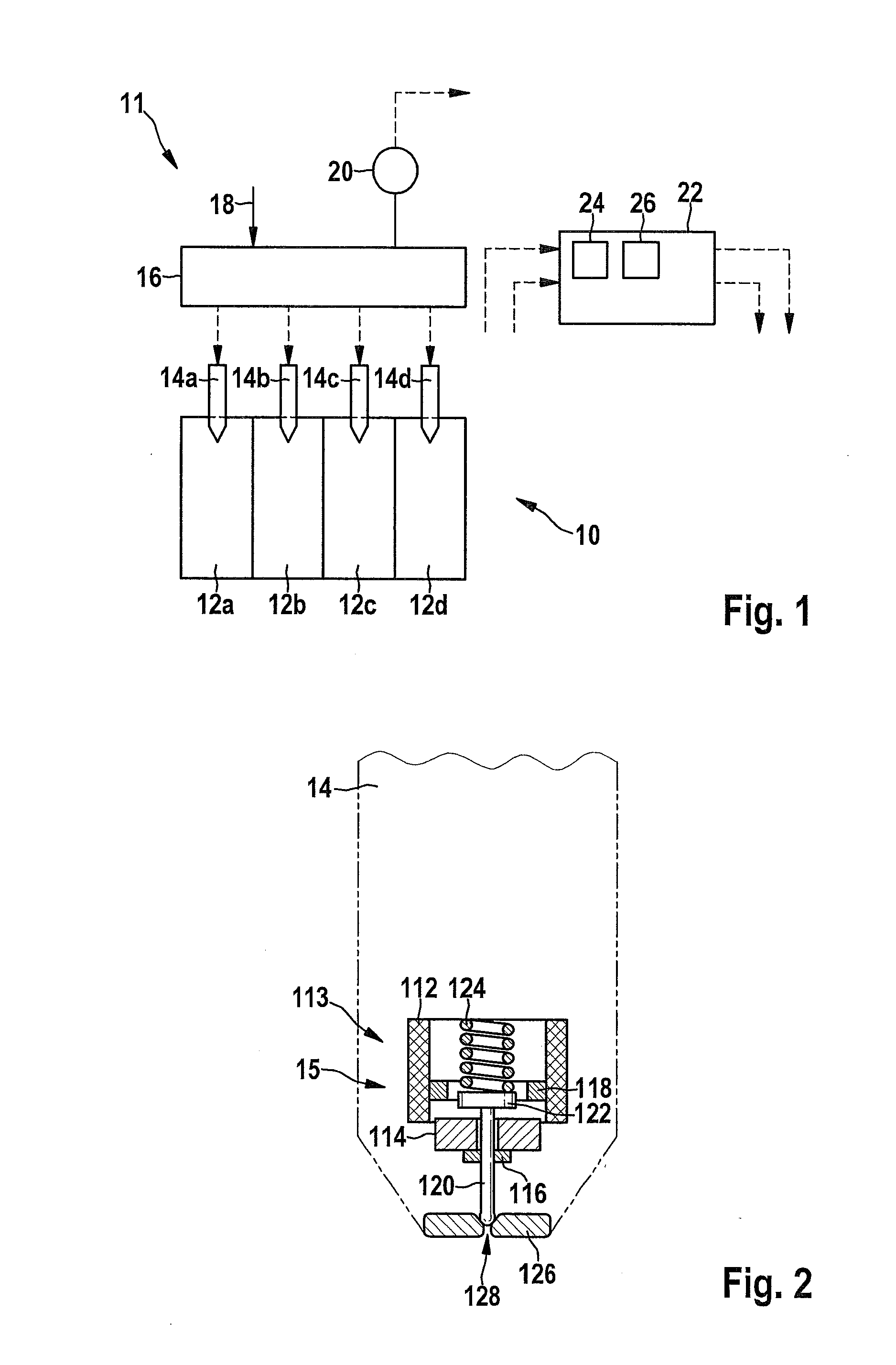
[0038]FIG. 1 shows a simplified diagram of a fuel system 11 of an internal combustion engine 10 having, in the present case, four cylinders 12 and associated, electrically actuated injectors (or injection valves) 14 for injecting fuel which are provided with indices a through d correspondingly to the cylinders of internal combustion engine 10, but are denoted in the following without indices in the event of general reference. In this specific example, injectors 14 are configured as electromagnetically actuated magnetic injectors. Injectors 14 may, however, also be configured as piezoelectric injectors, for example. Magnetic injectors 14 each have an electromagnetically actuated valve element 15 (cf. FIG. 2) which is not visible in FIG. 1. A common-rail block 16 which is supplied with fuel by a high-pressure line 18 and monitored by a pressure sensor 20 is illustrated upstream from magnetic injectors 14. Internal combustion engine 10 is configured either as a gasoline engine or as a ...


PUM


Abstract

A method for detecting an error in the opening behavior of an injector of an internal combustion engine, the injector having an electromagnetically actuated valve element, a ballistic partial injection being carried out, the injector being ballistically activated, so that the valve element is not opened up to a lift stop, a ballistic closing delay period is determined, the determined ballistic closing delay period is compared with a reference value, and an error in the opening behavior of the injector is detected with the aid of the comparison.

Description

RELATED APPLICATION INFORMATION[0001]The present application claims priority to and the benefit of German patent application no. 10 2013 222 603.9, which was filed in Germany on Nov. 7, 2013, the disclosure of which is incorporated herein by reference.FIELD OF THE INVENTION[0002]The present invention relates to a method for detecting an error in the opening behavior of an injector.BACKGROUND INFORMATION[0003]Injectors are known and are used in various ways, in particular as fuel injectors in internal combustion engines. Magnetic and piezoelectric injectors are widely used. A typical injector includes an electrically activatable valve element which may unblock and block a flow path of the fuel. The valve element includes a valve needle (or an injector needle) and a magnetic actuator (an armature or a magnet armature and a coil) or a piezoelectric actuator. The actuator is coupled to the valve needle and is electrically activated. The actuator and the valve needle are pressed by a val...

Claims


Application Information

Patent Timeline
Patent Type & Authority Applications(United States)
IPC IPC(8): F02M65/00F02M51/00
CPCF02M51/00F02M65/00F02D41/221F02M51/06F02D41/2438F02D41/2467F02D41/247F02D2041/2051F02M45/04F02M51/0603F02M65/005Y02T10/40
Inventor WILLIMOWSKI, MARKUSAMLER, MARKUSSCHENCK ZU SCHWEINSBERG, ALEXANDERSTIEF, FLORIANJOOS, KLAUS
Owner ROBERT BOSCH GMBH
Why Eureka
Try Eureka