Plug for well drilling provided with ring-shaped ratchet structure

a well and ratchet technology, applied in the direction of fluid removal, well accessories can solve the problems of substantial cost and time, pulverization, drilling out, etc., and the patent document 3 does not disclose whether a material contains a degradable material, so as to achieve the effect of reliably transporting and reducing the cost of well drilling steps

Inactive Publication Date: 2016-10-13
KUREHA KAGAKU KOGYO KK
View PDF3 Cites 11 Cited by
  • Summary
  • Abstract
  • Description
  • Claims
  • Application Information

AI Technical Summary

Benefits of technology

[0022]a) at least one of the members or the mandrel is formed from a degradable material, and
[0026]a1) the mandrel is formed from a degradable material;
[0028]b) a ring-shaped ratchet structure orthogonal to the axial direction of the mandrel is provided on an inner circumferential surface of at least one of the members and the outer circumferential surface of the mandrel, the ring-shaped ratchet structure being formed from a plurality of interlocking parts that allow movement of the member in one direction along the axial direction of the mandrel and restrict movement in the opposite direction.
[0055]A first aspect of the present invention provides a plug for well drilling comprising a mandrel and members attached on an outer circumferential surface orthogonal to an axial direction of the mand

Problems solved by technology

Because the plug is not designed to be released and retrievable after use, it is typically removed by destruction or by making it into small fragments by pulverization, drilling out, or another method, but substantial cost and time are required for pulverization, drilling out, and the like.
There are also plugs spec

Method used


Image

  • Plug for well drilling provided with ring-shaped ratchet structure
  • Plug for well drilling provided with ring-shaped ratchet structure
  • Plug for well drilling provided with ring-shaped ratchet structure

Examples


Embodiment Construction

[0074]The present invention relates to a plug for well drilling comprising a mandrel and members attached on an outer circumferential surface orthogonal to an axial direction of the mandrel, wherein:

[0075]a) at least one of the members or the mandrel is formed from a degradable material, and

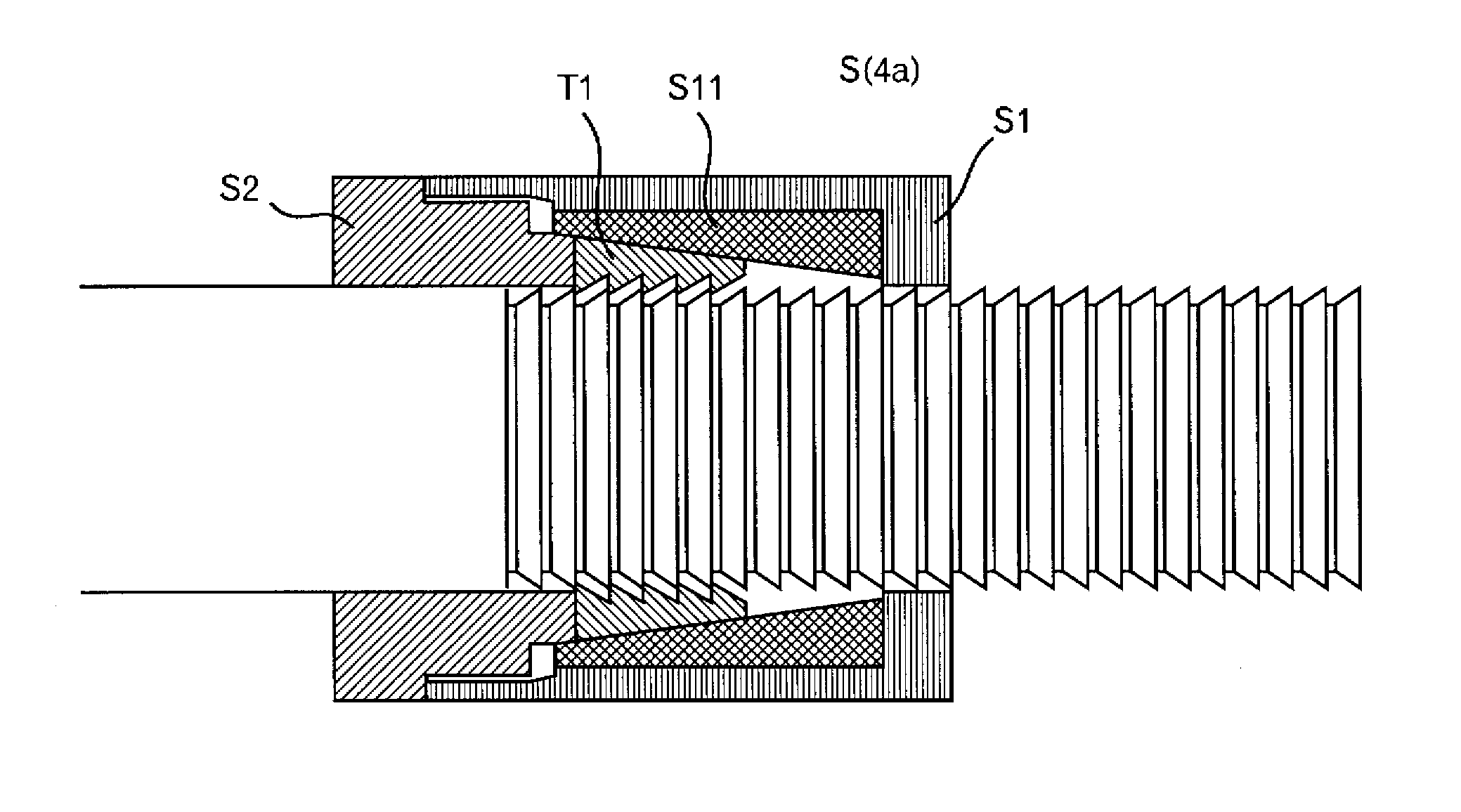
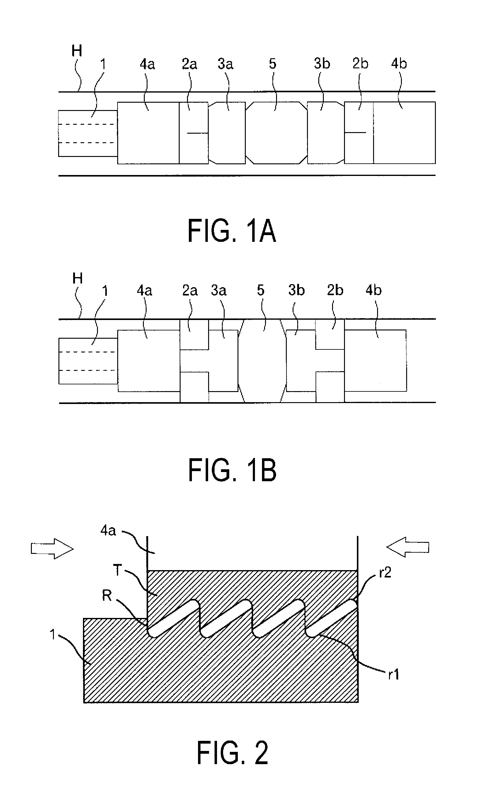
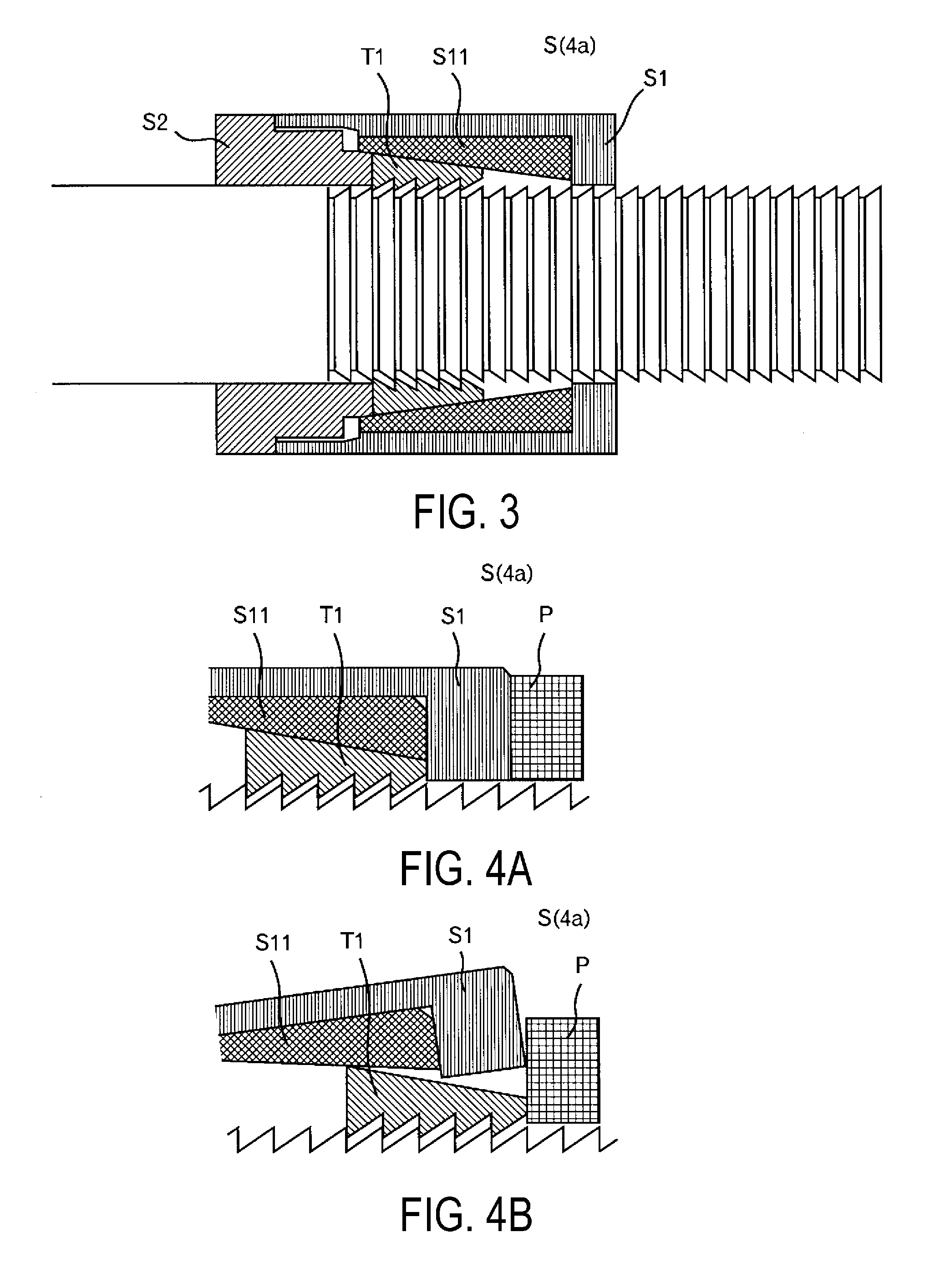
[0076]b) a ring-shaped ratchet structure orthogonal to the axial direction of the mandrel is provided on an inner circumferential surface of at least one of the members and the outer circumferential surface of the mandrel, the ring-shaped ratchet structure being formed from a plurality of interlocking parts that allow movement of the member in one direction along the axial direction of the mandrel and restrict movement in the opposite direction. The present invention is described below while referencing FIGS. 1A and 1B.

I. Plug for Well Drilling

1. Mandrel

[0077]The plug for well drilling of the present invention is provided with a mandrel and members attached on the outer circumferential surface or...


PUM


Abstract

A plug for well drilling comprising a mandrel and members attached on an outer circumferential surface orthogonal to an axial direction of the mandrel, wherein at least one of the members or the mandrel is formed from a degradable material; a ring-shaped ratchet structure formed from a plurality of interlocking parts that allows movement of the member in one direction along the axial direction of the mandrel and restricts movement in the opposite direction is provided on an inner circumferential surface of the member and the outer circumferential surface of the mandrel; preferably further comprising a pushing jig including a ratchet structure and a ring-shaped plate adjacent to the axial direction leading side of the pushing jig. Additionally, a well drilling method using the plug for well drilling, comprising degrading a part or all of the plug after blocking a borehole.

Description

TECHNICAL FIELD[0001]The present invention relates to a plug for well drilling used in well drilling for the purpose of producing hydrocarbon resources such as petroleum, natural gas, or the like; and a well drilling method.BACKGROUND ART[0002]Hydrocarbon resources such as petroleum, natural gas, and the like have been excavated and produced through wells (oil wells and gas wells; hereinafter referred to collectively as “wells”) having porous and permeable subterranean formations. As energy consumption increases, deeper wells are being drilled, reaching depths greater than 9000 m worldwide and greater than 6000 m in Japan. In wells that are continuously excavated, methods in which fluid pressure is used to form fractures in the productive layer (also called “fracturing” or “hydraulic fracturing”), for the purpose of continuously excavating hydrocarbon resources efficiently from subterranean formations of which permeability has decreased over time and subterranean formations of which...

Claims


Application Information

Patent Timeline
IPC IPC(8): E21B29/02E21B33/128C09K8/42E21B43/26
CPCE21B29/02C09K8/426E21B33/128E21B43/26E21B23/06E21B33/1208E21B33/1291
Inventor TAKAHASHI, TAKEOOKURA, MASAYUKI
Owner KUREHA KAGAKU KOGYO KK
Why Eureka
Try Eureka