

Connector assembly with strain relief member
- Summary
- Abstract
- Description
- Claims
- Application Information
AI Technical Summary
Benefits of technology
Problems solved by technology
Method used
Image


Examples
first embodiment
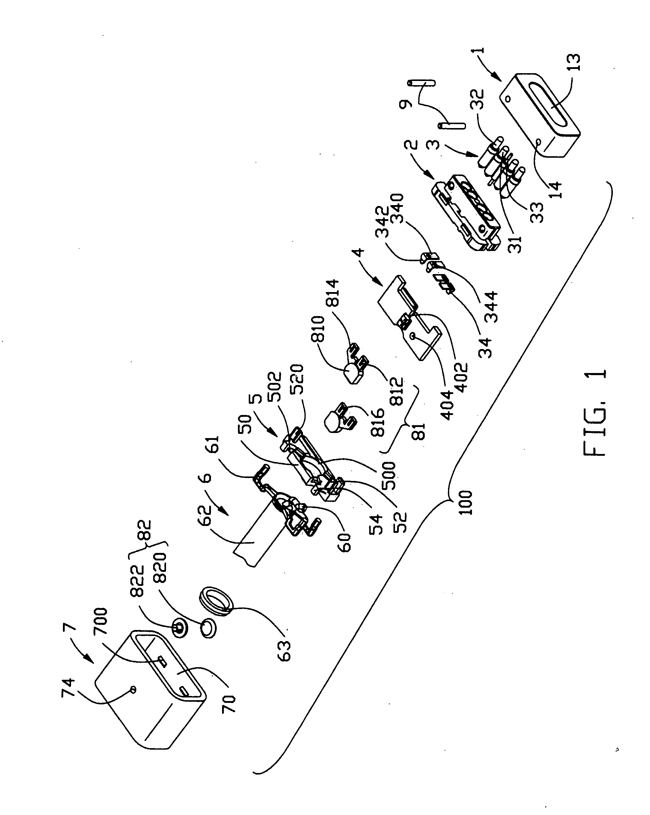
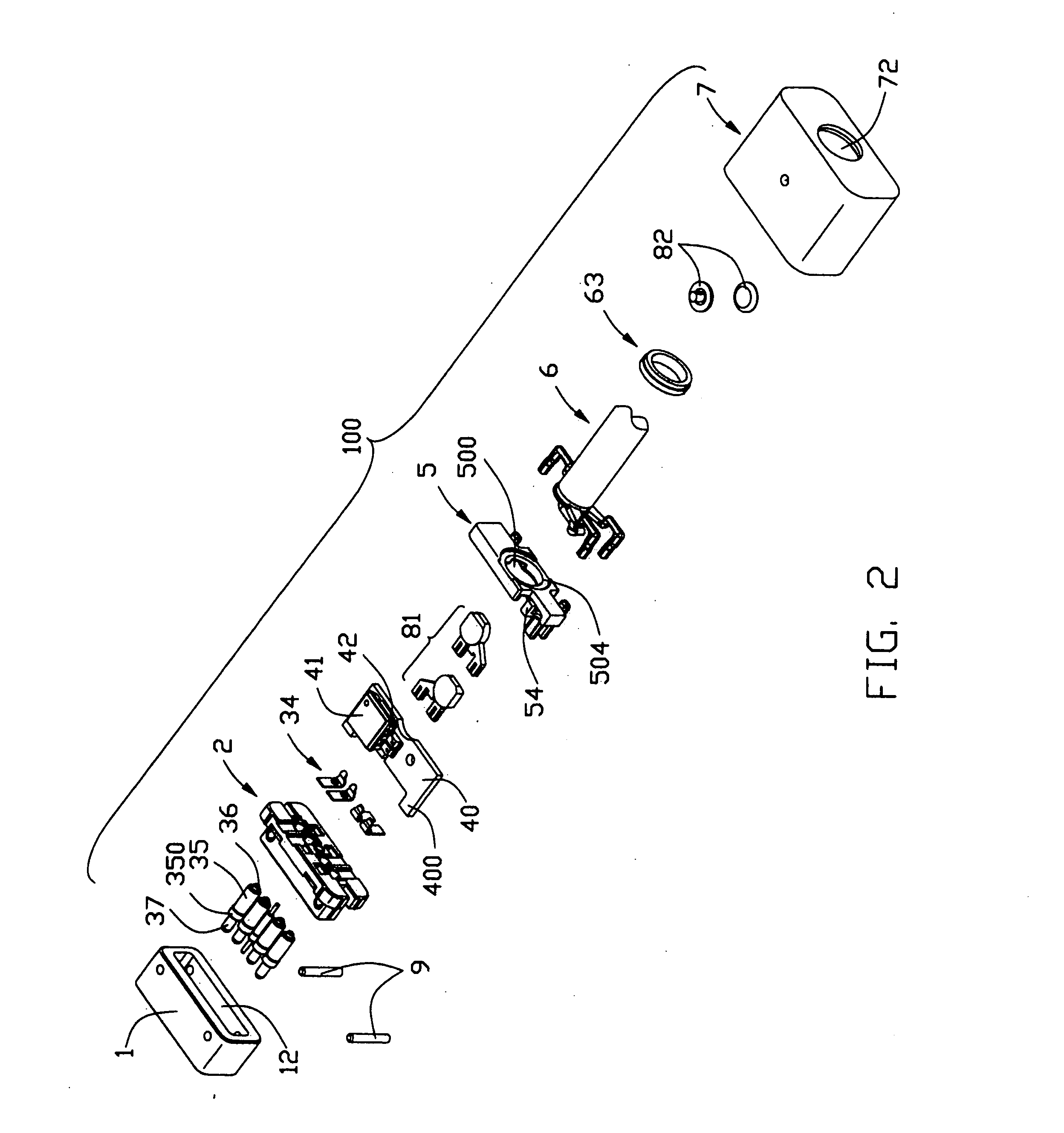
[0028]Referring to FIGS. 1-3, a connector assembly 100 in accordance with the present invention comprises a housing 2, a plurality of conductive contacts 3 assembled to the housing 1, a circuit board 4 assembled to the housing 1, a plurality of conductive elements 34 respectively electrically connecting with the contacts 3 and the circuit board 4, a strain relief member 5 assembled to and electrically connecting with the circuit board 4, a cable 6 electrically connecting with the die cast member 5 to achieve the electrical connection with the circuit board 4, front and rear covers 1, 7 respectively assembled to the housing 2 and together enclosing the elements mentioned above therebetween.
[0029]Please refer to FIGS. 3-4, the housing 2 comprises a base portion 21 and a tongue portion 22 extending forwardly from the base portion 21. The housing 2 defines two pairs of first receiving passages 23 and a center second passage 24 respectively recessed from a front face of the tongue portio...
second embodiment
[0043]A cable connector assembly 200 in accordance with the present invention is illustrated in FIGS. 17-23. Compared with the cable connector assembly 100, structures of the contacts 3′, the strain relief member 5′, the cable 6′ of the cable connector assembly 200 are different from those of the cable connector assembly 100. In addition, the cable connector assembly 200 further comprises a supporting member 64′ for assisting the metal braiding layer of the cable 6′ to be soldered with the strain relief member 5′ and has no conductive elements 34. Now, detail description to the structures different from those of the cable connector assembly 100 will be given hereinafter, and the same structures same as those of the cable connector assembly 100 are omitted here.
[0044]Since the cable connector assembly 200 has no conductive elements 34, thus, corresponding first and second rectangular recesses 215, 216 disclosed in the cable connector assembly 100 are omitted in the cable connector as...
third embodiment
[0047]Now referring to FIGS. 24-32, a cable connector assembly 300 in accordance with the present invention is illustrated.
[0048]The first difference between the cable connector assembly 300 and the cable connector assembly 100 is that the cable connector assembly 300 comprises a cosmetic element 2a″ assembled to the housing 2″ for cosmeticize the visual effect of the cable connector assembly 300. The cosmetic element 2a″ is of ellipse-shape and defines four first channels 25″ and a second channel 26″ corresponding to the first receiving passages 23 and the second receiving passage 24 of the housing 2″ with dimensions corresponding to the diameters of the contacting portions 37 of the contacts 3. An entranceway 27″ is recessed forwardly from a rear surface of the cosmetic element 2a″, thus, forming an inner front face 270″. A plurality of different-size passageways 28″ recess forwardly from the inner front face 270″ to communicate with corresponding first and second channels 25″, 26...
PUM
 Abstract
Description
Claims
Application Information