Portable power supplying device

a power supply device and portability technology, applied in parallel/serial switching, transportation and packaging, and the arrangement of several simultaneous batteries, etc., can solve the problems of inability to adjust for application, and inconvenient use of battery packs b>1/b>

Inactive Publication Date: 2008-01-10
HSIEH HSIN PEI
View PDF4 Cites 12 Cited by
  • Summary
  • Abstract
  • Description
  • Claims
  • Application Information

AI Technical Summary

Benefits of technology

[0015]According to the present invention, there is provided a portable power supplying device that includes a base, a battery terminal unit, a circuit switch assembly, and a switch control member. The base includes an output terminal, and is formed with first, second and third battery mounts adapted for receiving first, second and third battery members, respectively. The battery terminal unit includes a first battery terminal set disposed at the first battery mount, a second battery terminal set disposed at the second battery mount, and a third battery terminal set disposed at the third battery mount. The circuit switch assembly is connected to the first, second and third battery terminal sets, and is operable in a selected one of a series connection state, where the circuit switch assembly connects the first, second and third battery terminal sets such that the first, second and third battery members are connected in series, and a parallel connec

Problems solved by technology

1. The battery pack 1 is limited in that the output voltage cannot be adjusted according to different kinds of batteries, thereby making the battery pack 1 inconvenient to use:
In other words, the battery pack 1 is not suitable for a range of b

Method used


Image

  • Portable power supplying device
  • Portable power supplying device
  • Portable power supplying device

Examples


Embodiment Construction

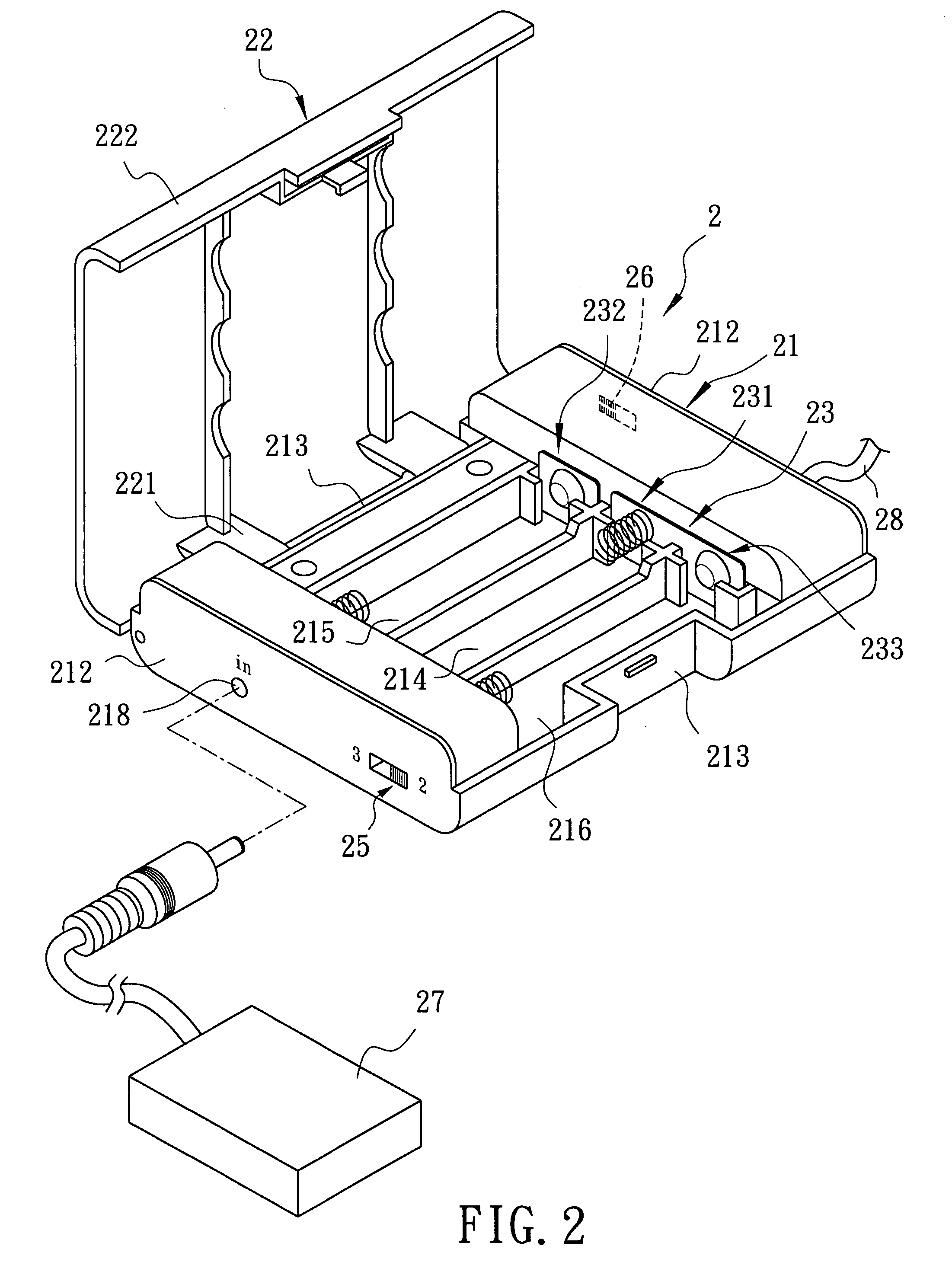
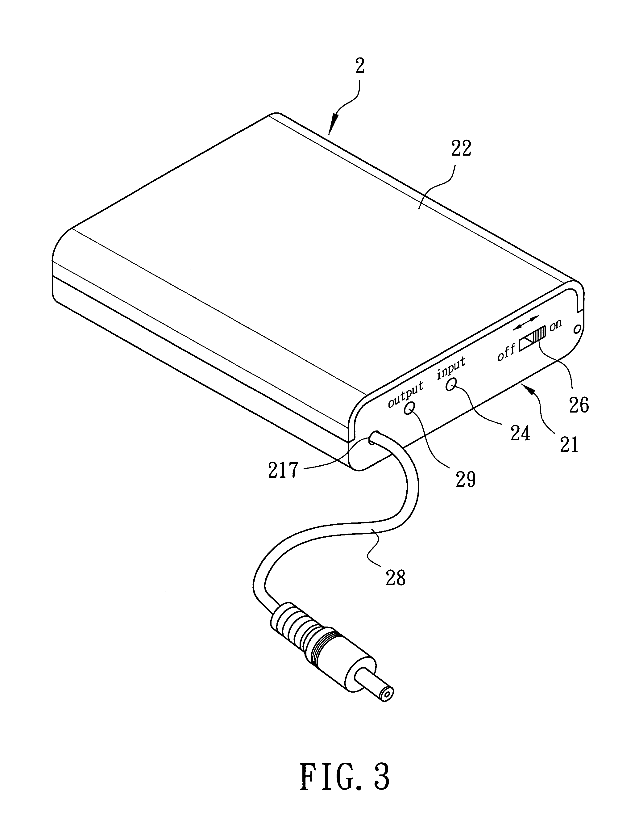
[0027]As shown in FIG. 2 and FIG. 3, the preferred embodiment of a portable power supplying device 2 according to the present invention includes abase 21, a cover 22, a battery terminal unit 23, a circuit switch assembly 25, a switch control member 26, a solar power generator 27, an output wire 28, a power-supply indicator 29, and a charging indicator 24. The base 21 is substantially rectangular in shape, and includes opposite control side walls 212, opposite engaging side walls 213 connected to the control side walls 212, an output terminal 217, and an input terminal 218. With further reference to FIG. 5-1, the base 21 is formed with first, second and third battery mounts 214, 215, 216 adapted for receiving first, second and third battery members 31, 32, 33, respectively. Each of the first, second and third battery members 31, 32, 33 can be a silver oxide battery, an alkaline battery, a manganese dioxide-zinc battery, etc.

[0028]In this embodiment, the first battery mount 214 is dis...


PUM


Abstract

A portable power supplying device includes: a base; a terminal unit including first, second and third terminal sets disposed at first, second and third mounts in the base, respectively; a circuit switch operable in a selected one of a series connection state, where the circuit switch connects the first, second and third terminal sets such that batteries disposed at the first, second and third mounts are connected in series, and a parallel connection state, where the circuit switch connects the second and third terminal sets such that the batteries disposed at the second and third mounts are connected in parallel; and a switch control operable in a selected one of a non-power supplying state, where the switch control breaks electrical connection between an output terminal and the terminal unit, and a power supplying state, where the switch control makes electrical connection between the output terminal and the terminal unit.

Description

CROSS-REFERENCE TO RELATED APPLICATION[0001]This application claims priority of Taiwanese Application No. 095210560, filed on Jun. 16, 2006.BACKGROUND OF THE INVENTION[0002]1. Field of the Invention[0003]The invention relates to a power supplying device, more particularly to a portable power supplying device.[0004]2. Description of the Related Art[0005]As shown in FIG. 1, U.S. Patent Application Publication No. 2005 / 0231155A1, entitled “Battery Pack with Power Input / Output”, discloses a battery pack 1 including a base 11, a cover 12 coupled removably to the base 11, a battery terminal unit 13, an output terminal 14 provided on one side of the base 11, an input terminal 15 provided on the side of the base 11 and adapted to connect to a commercial AC power source, and a switch control member 16 provided on the side of the base 11 and connected electrically to the output and input terminals 14, 15.[0006]The base 11 is formed with two battery mounts 111 spaced apart from each other, and...

Claims


Application Information

Patent Timeline
IPC IPC(8): H02J7/00
CPCH02J7/0024H02J7/0063H02J7/0045
Inventor HSIEH, HSIN-PEI
Owner HSIEH HSIN PEI
Why Eureka
Try Eureka