
Distractible intervertebral implant

Inactive Publication Date: 2008-01-10
ABBOTT SPINE INC
View PDF20 Cites 25 Cited by
  • Summary
  • Abstract
  • Description
  • Claims
  • Application Information

AI Technical Summary

Benefits of technology

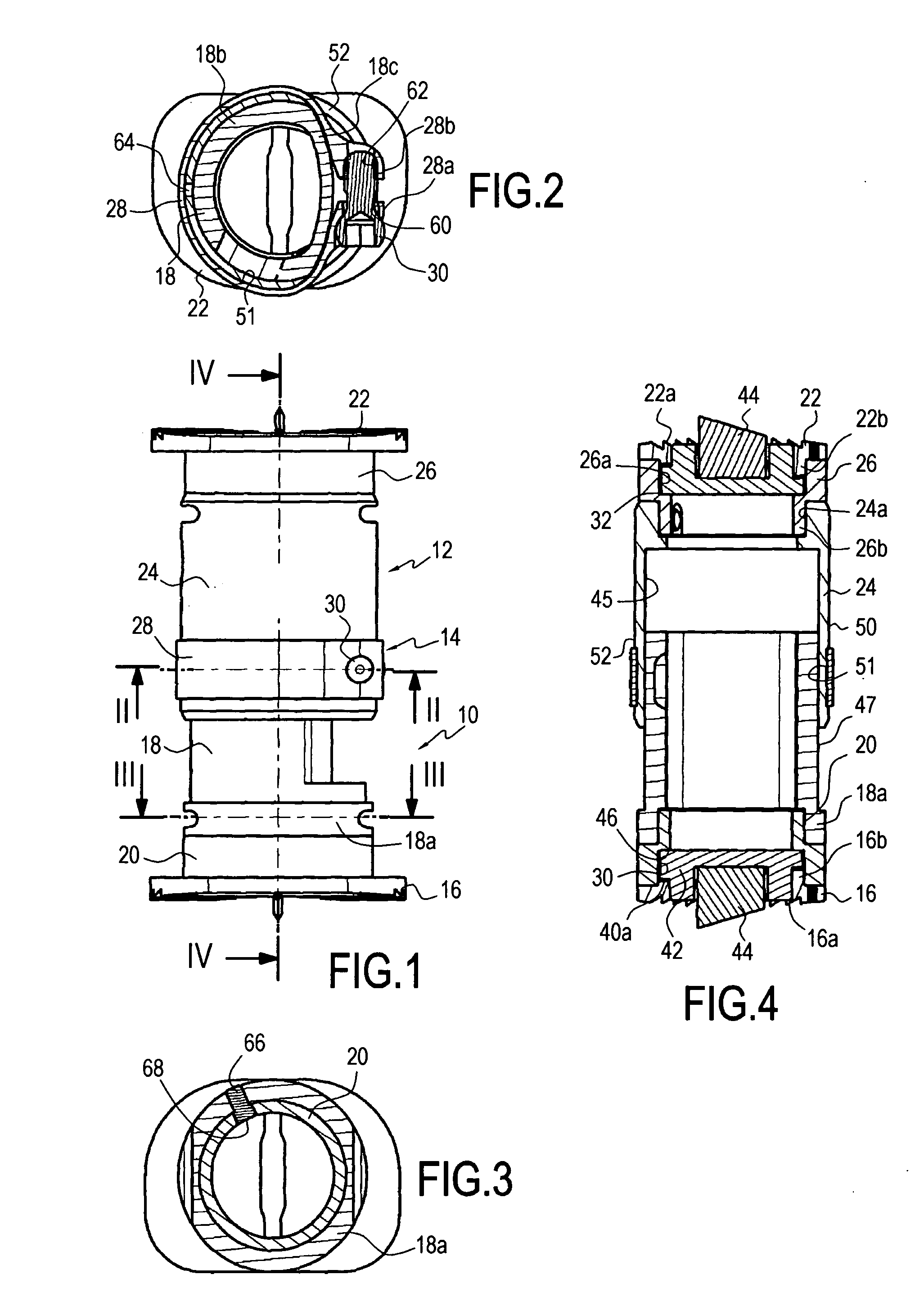
[0010] To achieve this object of the invention, the implant includes a first assembly constituted by a first prosthetic plate and a first spacer element having at least a portion of its outside surface that is cylindrical, the prosthetic plate being secured to the first spacer element; a second assembly constituted by a second prosthetic plate and by a hollow second spacer element having at least a portion of its inside surface that is cylindrical, the first end of the second spacer element being secured to the second prosthetic plate and the first spacer element being suitable for sliding in the second spacer element; and means for preventing the first spacer element from moving in translation or in rotation relative to the second spacer element, the means having a clamping collar surrounding a portion of the outside surface of the second spacer element, and a lock screw for tightening the collar onto the second spacer element in such a manner that the elastic deformation of the second spacer element holds the two spacer elements together, thereby enabling the distance between the two prosthetic plates to be adjusted.
[0011] It will be understood that by means of the characteristics of the invention, once the surgeon has adjusted the distance between the two prosthetic plates using the external distraction instrument, it suffices for the surgeon to act on the screw associated with the clamping collar to ensure that the two spacer elements cannot move relative to each other. This is achieved by the elastic deformation produced by tightening the collar against the outside face of the second spacer element. It will be understood that such a fastening technique enables the distance between the prosthetic plates to be adjusted continuously.
[0016] This disposition makes it possible to adapt the direction of the anchor element to the surgical technique used for putting the intervertebral implant into place.

Problems solved by technology

Those implants present the drawback of being relatively complex because of the presence of the mechanism for distracting the prosthetic plates.
It will be understood that such a system for interconnecting the cylinders on which the prosthetic plate are mounted present the drawback of not allowing the distance between the prosthetic plates to be adjusted continuously, since it is necessary to provide blind holes in the inside cylinder for receiving the cone-point screws, which are themselves mounted in the outside cylinder.

Method used


Image

  • Distractible intervertebral implant
  • Distractible intervertebral implant
  • Distractible intervertebral implant

Examples


Embodiment Construction

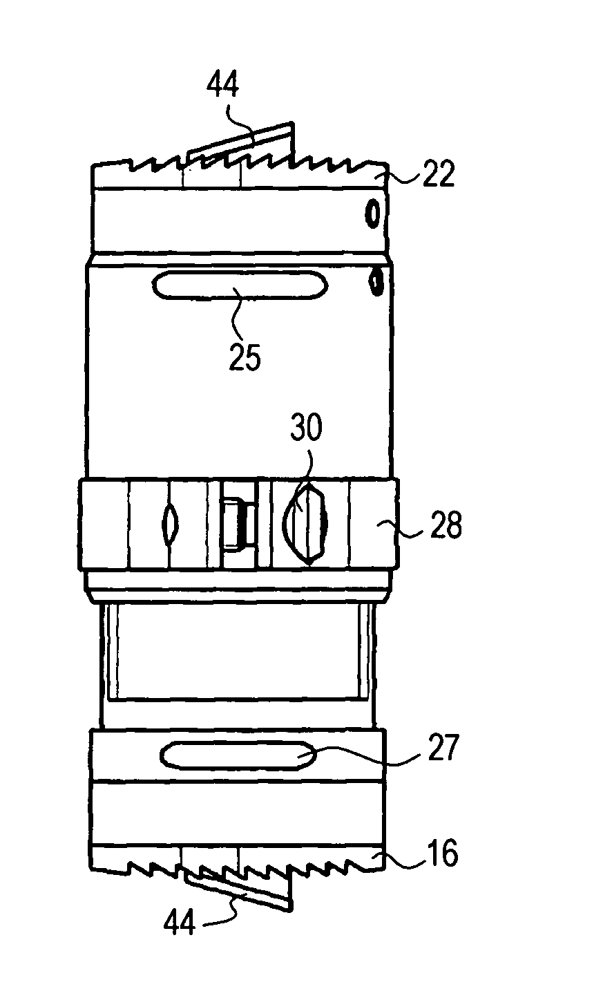
[0027] As can be seen in FIG. 1, the distractible vertebral implant is constituted by a first or bottom assembly 10, by a second or top assembly 12, and by means 14 for securing the assemblies 10 and 12 to each other, and constituted in the embodiment shown by a clamping collar 14.

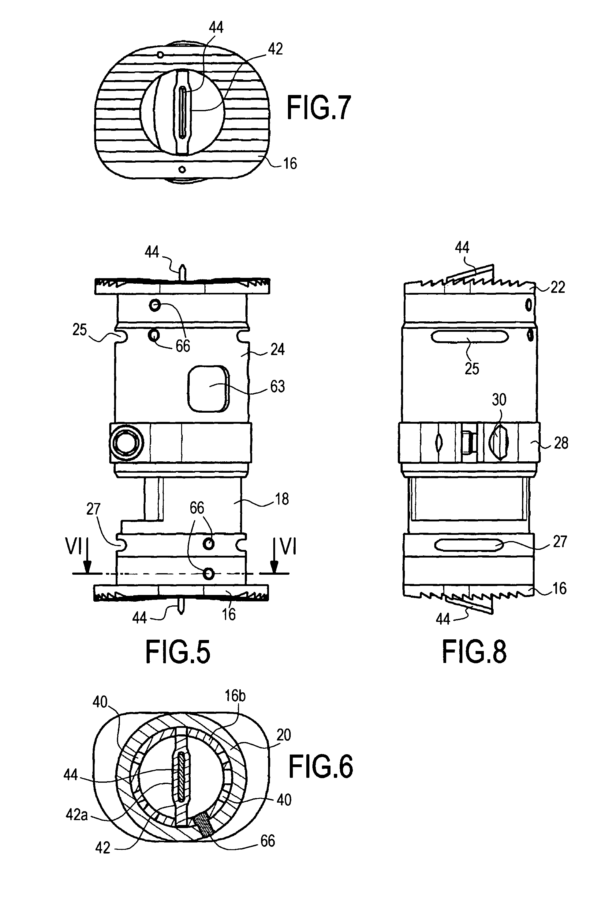
[0028] In the embodiment shown in FIG. 1, the first assembly 10 is constituted by a bottom prosthetic plate 16, a bottom spacer element 18, and a distance piece 20. Similarly, the second or top assembly 12 is constituted by a top prosthetic plate 22, a top spacer element 24, and a top distance piece 26. The fastener means 14 are constituted by a clamping collar 28 and a clamping screw 30.

[0029] In principle, the first spacer element or bottom spacer element 18 is mounted telescopically in the top spacer element 24. With the help of an external distracter instrument engaged in notches 25 and 27 formed at the ends of the spacer elements 18 and 24, this enables the surgeon to adjust the distance between the...


PUM


Abstract

The invention relates to a distractible intervertebral implant having a first assembly (10) constituted by a first prosthetic plate (16) and a first spacer element (18), the prosthetic plate being secured to the first spacer element; a second assembly (12) constituted by a second prosthetic plate (22) and by a hollow second spacer element (24), having a first end secured to the second prosthetic plate and the first spacer element being suitable for sliding in the second spacer element; and means (14) for preventing the spacer element from moving in translation or in rotation relative to each other, the means having a clamping collar (28) surrounding a portion of the outside surface of the second spacer element, and a lock screw (30) for tightening the collar onto the second spacer element.

Description

RELATED APPLICATION [0001] This application claims priority to French Patent Application No. 0652544, filed Jun. 20, 2006, which application is assigned to the assignee of the present invention and the entire contents of which are incorporated herein by reference. TECHNICAL FIELD [0002] The present invention relates to a distractible intervertebral implant. BACKGROUND OF THE INVENTION [0003] So-called “replacement” intervertebral implants serve to replace one or two vertebral bodies together with their associated disks after one or two vertebrae have been removed in part. This type of implant is thus disposed between the vertebral bodies of two vertebrae. At each of its ends, the implant itself has a respective prosthetic plate for anchoring in an adjacent vertebral body, these vertebral plates usually being fitted with portions in relief firstly to provide effective anchoring of the prosthetic plates in the vertebral plates, and also to damage the plates in such a manner as to enco...

Claims


Application Information

Patent Timeline
IPC IPC(8): A61F2/44A61B17/58
CPCA61F2/44A61F2002/30471A61F2002/30235A61F2002/30497A61F2002/305A61F2002/30507A61F2002/3054A61F2002/3055A61F2002/30594A61F2002/30601A61F2002/30772A61F2002/30845A61F2002/30884A61F2002/4475A61F2220/0025A61F2230/0069A61F2002/2835A61F2002/30495A61F2002/30593
Inventor DOUGET, STEPHANELE COUEDIC, REGISLARROQUE-LAHITETTE, GILLES
Owner ABBOTT SPINE INC
Learn More