Pressure Control Valve

a technology of pressure control valve and control valve, which is applied in the direction of functional valve types, lighting and heating apparatus, refrigeration components, etc., can solve the problems of controlling valve size increase, control pressure greatly deviating, cop dropping, etc., to prevent abnormal high pressure, reduce cop, and reduce the effect of cop

Inactive Publication Date: 2008-01-17
DENSO CORP +1
View PDF7 Cites 6 Cited by
  • Summary
  • Abstract
  • Description
  • Claims
  • Application Information

AI Technical Summary

Benefits of technology

[0012] In view of the problems described above, it is an object of the present invention to provide a pressure controlling valve for use in a supercritical cycle, particularly in a refrigeration cycle using CO2 for a refrigerant, that can restrain a control pressure from changing owing to displacement of a resilient member and can prevent an abnormal high pressure and drastic drop of COP (performance coefficient).
[0013] It is a second object of the invention to provide a pressure controlling valve capable of making small a sealed space (temperature sensitive portion) into which a gas is sealed, and holding down the increase of the size and production cost of the valve.
[0014] It is a third object of the invention to provide a pressure controlling valve capable of reducing a high pressure and preventing the drop of durability of an apparatus and rise of a discharge temperature.

Problems solved by technology

However, the pressure controlling valve according to Japanese Unexamined Patent Publication No. 9-264622 has the problem that when the change of the control pressure is greater than the diaphragm displacement, the control pressure greatly deviates from the high pressure (optimal pressure) at which COP (Coefficient of Performance) reaches a maximum, and COP drops.
Accordingly, the pressure controlling valve becomes larger in size and production cost becomes higher.
When the high pressure becomes higher, there are problems that durability of the apparatus drops and the temperature of discharging the refrigerant becomes higher.

Method used


Image

  • Pressure Control Valve
  • Pressure Control Valve
  • Pressure Control Valve

Examples


first embodiment

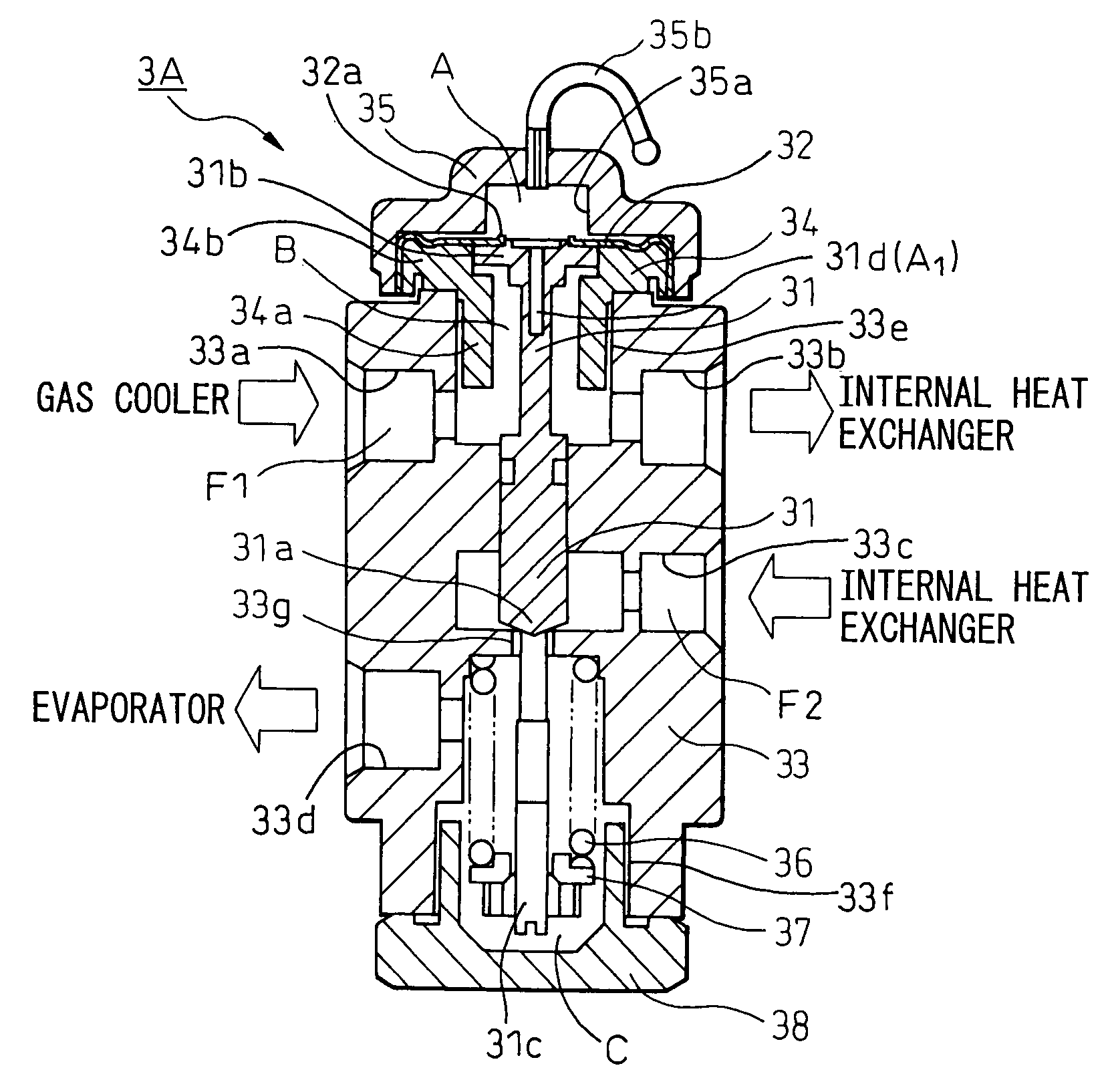
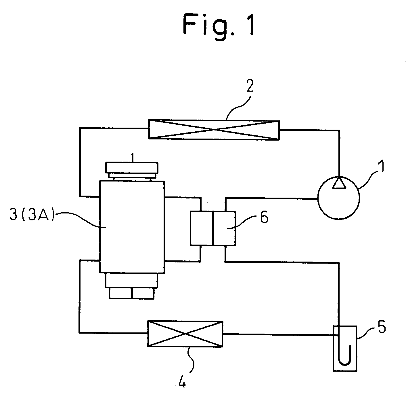
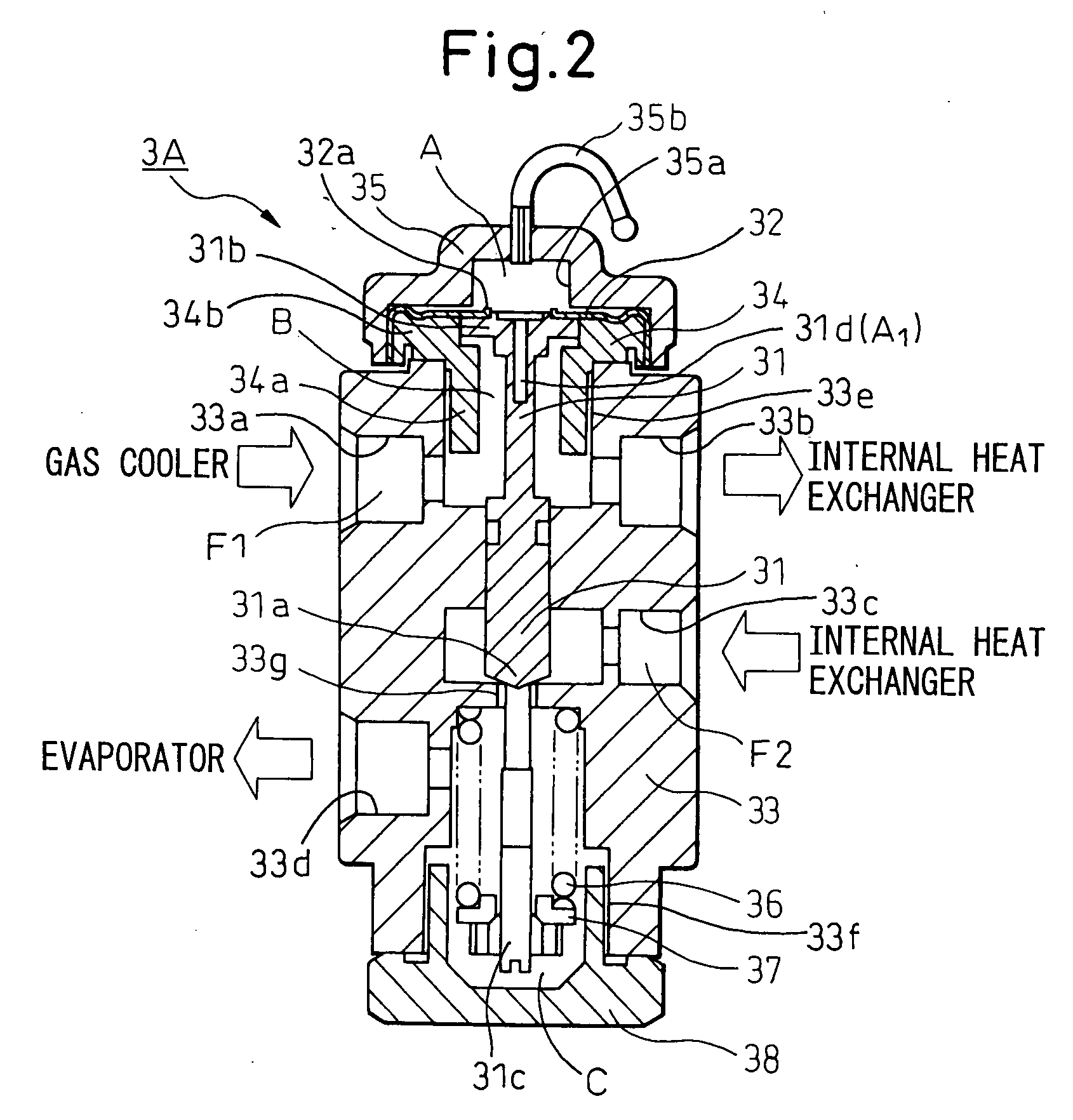
[0041] The pressure controlling valves according to embodiments of the present invention will be hereinafter explained with reference to the drawings. FIG. 1 is an explanatory view explaining a refrigeration cycle (supercritical refrigeration cycle) into which an internal heat exchanger is assembled, and which circulates CO2 as a refrigerant. FIG. 2 shows a pressure controlling valve according to the present invention that is applied to the refrigeration cycle shown in FIG. 1. In FIG. 1, reference numeral 1 denotes a compressor that sucks in and compresses a CO2 refrigerant and reference numeral 2 denotes a gas cooler (heat radiator) that cools the refrigerant compressed by the compressor 1.

[0042] Reference numeral 3 denotes a pressure controlling valve (expansion valve) according to this embodiment. This pressure controlling valve 3 has a temperature sensitive portion (sealed space) A into which CO2 gas is sealed, and controls refrigerant pressure on the exit side of the gas cooler...

second embodiment

[0074]FIG. 3 is an explanatory view useful for explaining the refrigeration cycle of the CO2 refrigerant without incorporating the internal heat exchanger. FIG. 4 shows a pressure controlling valve 3B according to the invention that is applied to the refrigeration cycle shown in FIG. 3. The same reference numeral is used to identify the same constituent member as in FIG. 1. In other words, reference numeral 1 denotes the compressor for sucking and compressing the CO2 refrigerant. Reference numeral 2 denotes the gas cooler for cooling the refrigerant compressed by the compressor 1. The pressure controlling valve 3 (3B) for controlling the refrigerant pressure on the exit side of the gas cooler 2 on the basis of the refrigerant temperature on the exit side of the gas cooler 2 is arranged on the exit side of the gas cooler 2 and operates as a pressure reducing device for reducing the pressure of the high pressure refrigerant.

[0075] Reference numeral 4 denotes the evaporator for evapora...


PUM


Abstract

In a pressure controlling valve 3 for causing deformation of a resilient member 32 by a pressure difference between a CO2 gas pressure in a sealed space (heat sensitive portion) corresponding to a refrigerant temperature and a high pressure of the CO2 refrigerant in the refrigeration cycle to open and close the valve, a volume ratio Vs / (Vs−Vo) of a total volume (Vs) of the sealed space when the valve is fully closed and a total volume (Vo) of the sealed space when the valve is fully open is greater than 1.9 or 2.4. To improve this volume ratio, a cavity 31d communicating with the sealed space is formed inside a displacement transmission member 31 coupled with the resilient member, or a recess portion 35a is formed in a cover member 35a, or a member communicating with the sealed space is connected.

Description

BACKGROUND OF THE INVENTION [0001] 1. Field of the Invention [0002] This invention relates to a pressure controlling valve (expansion valve) for controlling exit side pressure of a heat radiator (gas cooler) of a vapor compression system refrigeration cycle. More particularly, the invention is suitable for a supercritical refrigeration cycle using a refrigerant, such as carbon dioxide (CO2) in a supercritical zone. [0003] 2. Description of the Related Art [0004] In a refrigeration cycle using HFC134a as a refrigerant according to the prior art, a pressure controlling valve, such as the one disclosed in Japanese Unexamined Patent Publication No. 2002-13844 and shown in FIG. 14 has been used to control a degree of superheat of an evaporator exit refrigerant. This pressure controlling valve 3 includes a temperature sensitive portion 3a, the internal pressure of which changes in accordance with a refrigerant temperature on the exit side of an evaporator 4, a film-like diaphragm 3c parti...

Claims


Application Information

Patent Timeline
Patent Type & Authority Applications(United States)
IPC IPC(8): F16K17/04
CPCF25B9/008F25B41/062F25B2500/01F25B2341/0683F25B2309/061Y10T137/7922F25B41/335
Inventor OHTA, HIROMIKAKEHASHI, NOBUHARUMATSUDA, RYOYANAGISAWA, SHU
Owner DENSO CORP
Why Eureka
Try Eureka