piston pump

A piston pump and piston technology, applied in the direction of piston pump, pump, pump components, etc., can solve the problems of reduced reliability, insufficient discharge, and deviation of processing dimensions, and achieve high reliability, cost reduction, and prevention of abnormality. The effect of high pressure

Active Publication Date: 2011-12-14
DAIKIN IND LTD +1
View PDF2 Cites 0 Cited by
  • Summary
  • Abstract
  • Description
  • Claims
  • Application Information

AI Technical Summary

Problems solved by technology

In the pump disclosed in the above-mentioned Patent Document 2, although the above-mentioned abnormal state is avoided by the reverse safety valve etc. installed in the piston chamber, the reverse safety valve etc. , when foreign matter such as dust is mixed into the gap between the check valve and its engaging hole, it is easy to produce a problem that it cannot be pushed away and returned to the original position only by spring force, and the reliability of the pump is significantly reduced.
[0009] (2) In order to pressurize and feed lubricating oil, it is desirable to open the communication path communicating with the discharge port while closing the suction port, but due to the difference in the angle of the eccentric cam that drives each piston with a predetermined phase difference or the It is difficult to process, assemble, and set in such a way that the communication path is opened while closing the suction port due to the deviation of the processing dimensions of each component
Therefore, when using high-viscosity lubricating oil or at low temperature, the discharge volume will be insufficient due to insufficient suction.

Method used


Image

  • piston pump
  • piston pump
  • piston pump

Examples


no. 1 approach

[0091] [Structure of Piston Pump 1 of First Embodiment]

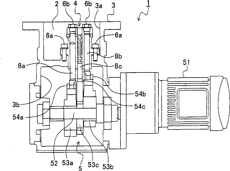
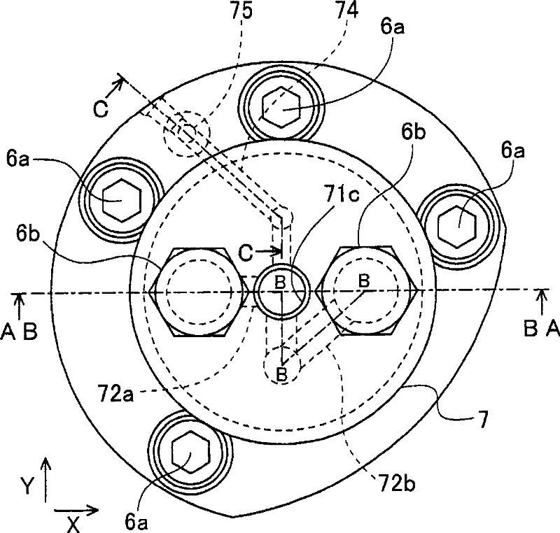
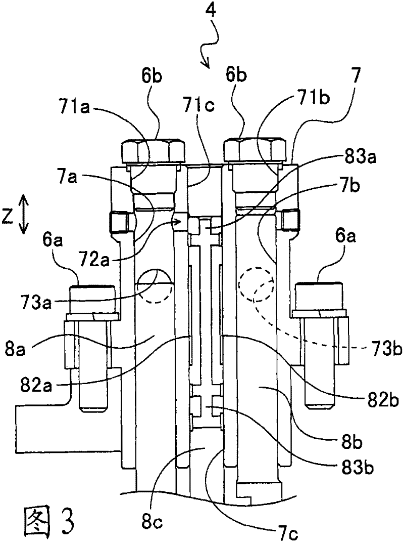
[0092] First, refer to Figure 1 to Figure 6 The structure of the piston pump 1 of the first embodiment will be described in detail. The piston pump 1 of this embodiment has a function of pressurizing and feeding lubricating oil 2 such as grease, and is mainly used in a centralized lubricating oil device. Such asfigure 1 As shown, the piston pump 1 has: a housing 3 having a lubricating oil storage chamber 3a for storing lubricating oil 2; a discharge mechanism part 4 which discharges the lubricating oil 2 stored in the lubricating oil storage chamber 3a; The mechanism part 5 drives the discharge mechanism part 4 .

[0093] The lubricating oil storage chamber 3a is provided in the upper part of the housing 3, and the drive chamber 3b which accommodates the drive mechanism part 5 is provided in the lower part. The discharge mechanism part 4 is attached to the bottom of the lubricating oil storage chamber 3a via a plura...

no. 2 approach

[0135] [Structure of Piston Pump 1 of Second Embodiment]

[0136] First, refer to Figure 13 The structure of the piston pump of the second embodiment will be described in detail. In addition, below, the same code|symbol as 1st Embodiment shows the same structure as 1st Embodiment.

[0137] In this second embodiment, the configuration other than the discharge mechanism is the same as that of the above-mentioned first embodiment, and therefore description thereof will be appropriately omitted. Such as Figure 13 As shown, in the main body portion 107 of the discharge mechanism portion 104 of the piston pump according to this embodiment, a suction passage 176 having a suction port 177 for sucking the lubricating oil 2 from the oil tank line is provided. This suction passage 176 communicates with a connection passage 183b formed in a pilot piston 108c described later, thereby communicating with the piston chamber 7c and the lubricating oil storage chamber 3a.

[0138] In the ...


PUM


Abstract

The present invention provides a piston pump. The piston pump (1) uses the ring lands (81a, 81b) that move with the reciprocating action of the pilot piston (8c), in the discharge line communicated with the oil discharge path (82a, 82b) and with the connection path (83a, 83b) ) to switch the piston chamber communication paths (72a, 72b) between the tank lines that communicate with each other. Thereby, when the main pistons (8a, 8b) move upward, the lubricating oil is pressurized and fed to the discharge line via the piston chamber communication passage and the oil discharge passage. In addition, when the main piston moves downward, the piston chambers (7a, 7b) communicate with the tank line via the piston chamber communication passage and the connection passage, so that abnormally high pressure in the piston chamber can be prevented.

Description

technical field [0001] The present invention relates to a piston pump for pressure-feeding lubricating oil such as grease. Background technique [0002] Conventionally, there is known a piston pump in which a suction port is provided in a main piston chamber and a discharge port is provided in a sub-piston chamber, and a pilot piston (pilot piston) arranged in the sub-piston chamber and a pilot piston arranged in the main piston chamber are arranged together. The reciprocating motion of the main piston is synchronized with the reciprocating motion, thereby discharging the lubricating oil introduced from the suction port from the discharge port (for example, refer to Patent Document 1). [0003] However, in the piston pump disclosed in the aforementioned Patent Document 1, the discharge is performed only once during one rotation of the rotation shafts of the main piston and the pilot piston. In the lubricating oil discharge step, a predetermined driving force is required to ...

Claims


Application Information

Patent Timeline
Patent Type & Authority Patents(China)
IPC IPC(8): F04B53/10F04B7/04F04B9/10F04B23/06
CPCF04B7/04
Inventor 广瀬雄一来间彰纪山崎和宏
Owner DAIKIN IND LTD
Why Eureka
Try Eureka