
Fluid coupling with disposable connector body

a technology of connector body and fluid, which is applied in the direction of couplings, pliable tubular containers, transportation and packaging, etc., can solve the problems of connectors still lacking suitable structures and couplings can become contaminated, so as to prevent contamination during connection

Active Publication Date: 2005-11-08
COLDER PRODS
View PDF15 Cites 80 Cited by
  • Summary
  • Abstract
  • Description
  • Claims
  • Application Information

AI Technical Summary

Benefits of technology

[0006]In accordance with the present invention, improvements upon existing fluid coupling designs have been made by providing a coupling apparatus with a disposable connector device on the dispensing side that is further directed to preventing contamination during connection.
[0016]The present invention provides a fluid coupling apparatus with improved connection capabilities and a connector on the dispensing side that is disposable after one time use to maintain cleanliness and prevent contamination. The coupling apparatus provides a recessed beveled end on the connector device so that connection is initiated before the membrane on the insert body is punctured, thereby preventing spill and squirting during connection. Further, the retention barb structures help avoid entrapment of product or a stagnant area by providing suitable seal and retaining properties.

Problems solved by technology

However, such couplings can become contaminated, particularly on the reusable connector side where contamination problems can occur after dispensing from a fluid source, such as dairy products and other non-shelf stable food items requiring clean environments.
For instance after dispensing is finished, such reusable connectors or couplers are mated with another insert body on a filled food source and may carry contaminants left from the previously emptied food source.
Further, such connectors still lack suitable structures to prevent product entrapment and product spill during connection from the food source insert or cap.

Method used


Image

  • Fluid coupling with disposable connector body
  • Fluid coupling with disposable connector body
  • Fluid coupling with disposable connector body

Examples


Embodiment Construction

[0033]In the following description of the illustrated embodiments, reference is made to the accompanying drawings that form a part hereof, and in which is shown by way of illustration of the embodiments in which the invention may be practiced. It is to be understood that other embodiments may be utilized as structural changes may be made without departing from the spirit and scope of the present invention.

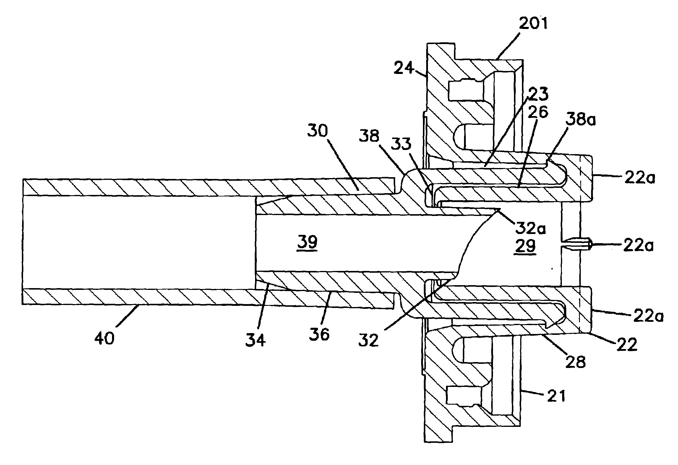
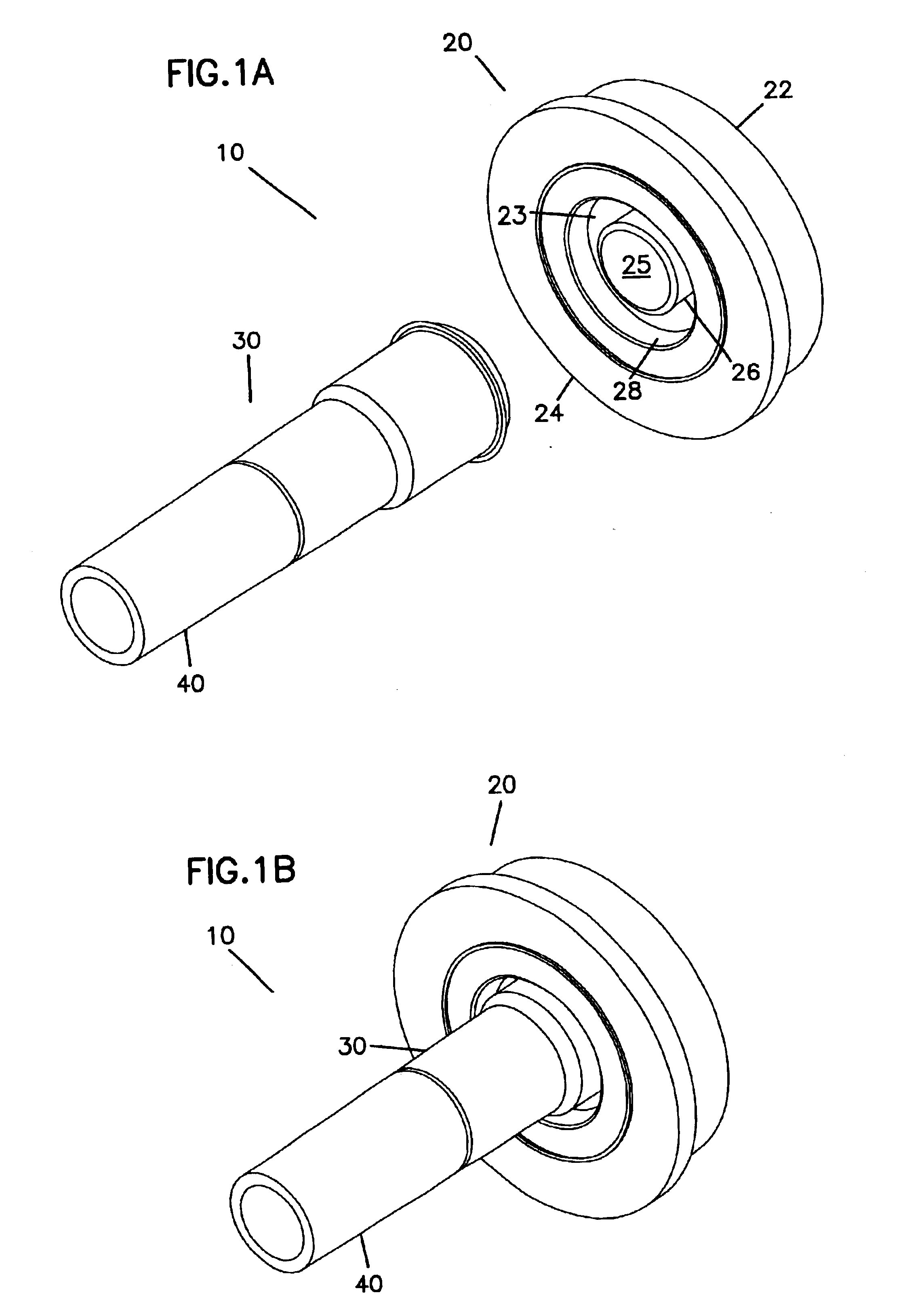
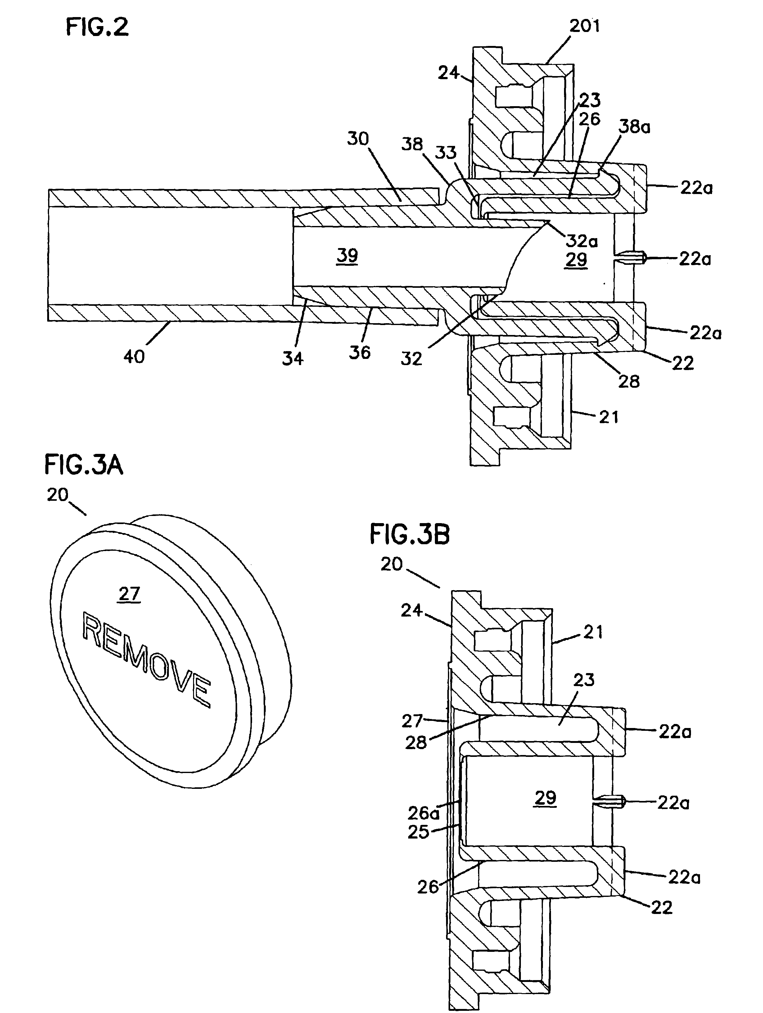
[0034]FIGS. 1A through 4 illustrate one preferred embodiment of a coupling apparatus 10 in accordance with the present invention. FIGS. 1A and 1B show the coupling apparatus 10 in a non-dispensing configuration and a dispensing configuration, respectively. The coupling apparatus includes an insert body 20 connectable with a connector device 30. Preferably, the insert body 20 is adaptable for connection with a fluid source including but not limited to a conventionally used bag or bag-in-box filled with foodstuffs, such as dairy products, beverages or other non-shelf stable food item...


PUM


Abstract

A coupling apparatus for fluid dispensing with a disposable connector on the fluid line or fluid dispensing system side. The coupling apparatus includes an insert body that is connectable with a disposable connector device. The insert body includes a recess area defined between a first inner sidewall and a second inner sidewall. The second inner sidewall extends coaxially with the first inner sidewall, and has an aperture defining an opening through a first and second end. The connector device includes a connector body connected with an adapter portion. The connector body includes a beveled end that is insertable through the aperture of the second inner sidewall. The adapter portion is disposed proximate and extends past the beveled end, where the beveled end is recessed within the adapter portion. An insertion space is defined between the beveled end and an outer wall defined by the adapter portion. The adapter portion is insertable into the recess area and the insertion space is receivable of the second inner sidewall.

Description

FIELD OF THE INVENTION[0001]The present invention relates generally to a coupling for fluid dispensing. More particularly, the present invention relates to a fluid coupling with a disposable connector body on the fluid line or fluid dispensing system side that connects with a fluid source.BACKGROUND OF THE INVENTION[0002]A variety of couplings and connectors are employed for fluid dispensing and are widely used in powered or gravity dispensing systems, for instance, in the dispensing of non-shelf stable food items.[0003]Typically, these fluid couplings use connection types that include an insert and / or cap connected with a fluid source, such as a bag or bag-in-box. The insert is coupled with a connector or coupler body that can access a fluid dispensing system, such as a fluid line. Many times, such connectors employ a piercing member at one end so as to puncture a membrane seal disposed on the insert when the connector is mated with the insert for fluid dispensing. Further, such co...

Claims


Application Information

Patent Timeline
IPC IPC(8): B65D5/74B65D77/06B65D25/48B67D1/00B65D25/38
CPCB65D5/746B65D25/48B65D77/068B67B7/26B67D1/0042B67D2001/0827B67D2210/00049
Inventor DECLER, CHARLES PETERJOHNSON, ROBERT K.
Owner COLDER PRODS
Learn More