Wavelength reconfigurable optical network

a technology of optical networks and reconfigurable optical networks, applied in the field of optical networks, can solve the problems of limiting the flexibility of wavelength assignment in the metro ring network, the possibility of wavelength reconfiguration and re-use, and the cost of current pon architectures

Active Publication Date: 2008-01-17
UNIVERSITY OF OTTAWA
View PDF6 Cites 78 Cited by
  • Summary
  • Abstract
  • Description
  • Claims
  • Application Information

AI Technical Summary

Benefits of technology

The invention describes a method of combining communication signals for transmission to end-users through a metro hub. These signals are transmitted through multiple wavelength channels without the need for conversion. The metro hub is located in a MRN and can be shared by multiple PONs. The MRN includes reconfigurable optical add-drop modules which can direct wavelength channels towards specific PONs and change the dropped channel selection. The ONUs have optical receivers with tunable filters and colorless transmitters that can transmit at different wavelengths. The invention allows for efficient use of network resources and facilitates bandwidth sharing through time domain multiplexing.

Problems solved by technology

The technical problem addressed in this patent text is to provide a more cost-effective and flexible optical network architecture for metro-access, which allows for wavelength re-configuration and re-use at the metro-PON interface and in the metro-area network. The current prior-art optical networks have significant costs associated with them, and do not provide flexibility in wavelength assignment and re-use.

Method used


Image

  • Wavelength reconfigurable optical network
  • Wavelength reconfigurable optical network
  • Wavelength reconfigurable optical network

Examples


numerical example

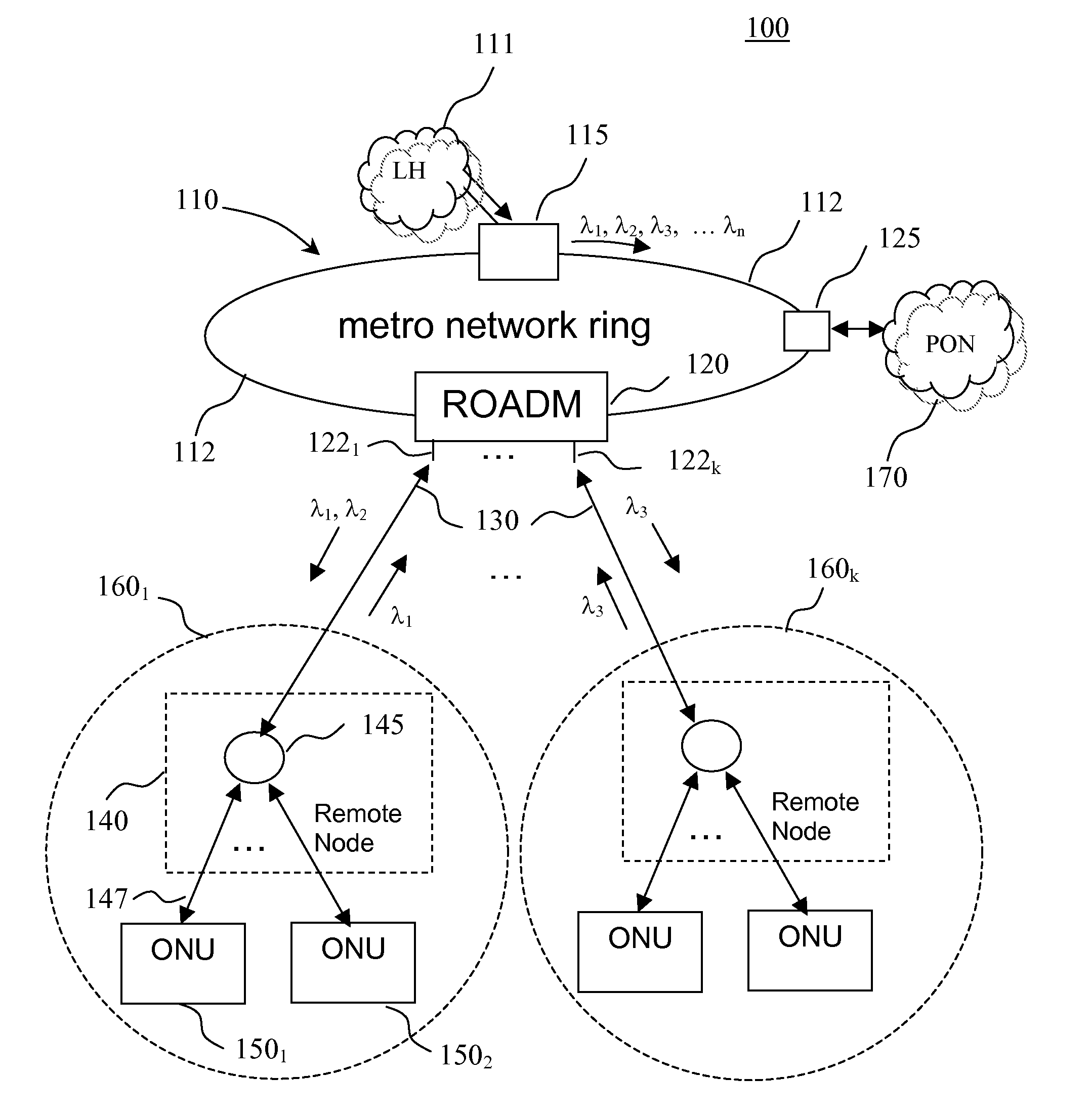
[0064]By way of example, the optical network of FIG. 5 has the following parameters: the length of optical fiber link between the metro hub 115 and the ROADM 120 is 10 km, the length of the trunk optical link 135 is 10 km, output power of the metro-hub transmitters is 5 dBm, output power of the ONU transmitters 3 dBm; insertion loss of optical devices in the wavelength path between the ONU transmitter / receiver and the metro hub transmitter / receiver: AWG 315—3 dB, circulator—1 dB, optical fiber loss—0.25 dB / km, ROADM—5 dB, optical splitter at the remote node 140—12 dB corresponding to 1×16 splitter, ONU optical coupler—3 dB, tunable filter—1 dB. This corresponds to a typical value of the overall optical loss associated with a wavelength path between the metro hub 115 and an ONU 150 of about 30 dB, so that the ONU transmitter and the ONU receiver each receive a downstream optical signal of about −25 dBm, while optical power of the upstream wavelength channel received by a metro hub re...


PUM


Abstract

The invention provides a unified optical network architecture for metro and access communication networks, wherein a metro ring network interfaces access PONs through one or more reconfigurable Optical Add/Drop Multiplexers to provide wavelength-reconfigurable all-optical transmission of communication signals from the metro ring network to designated optical network units associated with the end-users, and wherein one metro hub located in the metro ring network is utilized to set transmission wavelengths and timing for both downstream and upstream signal transmission for multiple access PONs.

Description


Claims


Application Information

Patent Timeline
Owner UNIVERSITY OF OTTAWA
Why Eureka
Try Eureka