Peg board mounting device

a technology for mounting devices and peg boards, which is applied in the direction of lightening support devices, washstands, scaffold accessories, etc., can solve the problems of not being able to attach to the board properly, becoming more of a slot, and therefore unusable, and achieve the effect of maximizing the useable spa

Inactive Publication Date: 2008-01-17
ZASLOFF DAVID
View PDF13 Cites 12 Cited by
  • Summary
  • Abstract
  • Description
  • Claims
  • Application Information

AI Technical Summary

Benefits of technology

[0014] The present invention provides the benefits of using only one hole to attach to a perforated surface via a fastener that will hold all sides of the hole. Since the device has no need to hang off the hole, the hole directly below it will be available for use. If a user decided to hang an item below the fastener they would be able to use the hole directly below the one in use by either a conventional hook or another magnet with a lesser offset. This will allow users to maximize the useable space on the perforated surface. When a magnetic holding element is used, one item can be secured to the magnet and another item can hang from the mounting surface. Further, an item hung on the mounting surface can be more securely held on the mounting apparatus by the magnet. Still further, the invention enables the mounting apparatus to be removable so that the mounting apparatus can be moved from a first hole to a second hole.

Problems solved by technology

One problem with this type of hook is that when an item is placed on the hook all its weight is supported by the bottom of a hole the hook is inserted into.
This load causes these holes to become oblong or deformed over time and can lead to the hook not attaching to the board properly or the hole itself becoming so deformed it becomes more of a slot and therefore unusable.
Another problem with these hooks is that they must hang off the hole causing one or more holes beneath the hole that the hook is inserted in to be covered by the hook itself or by an object hanging off the hook rendering the covered holes unusable.
Still another problem is that perforated boards can come in different thicknesses and having varying hole diameters.
When hooks of uniform dimension are used they can fall off very easily when an item being held is removed by a user and the hook does not properly correspond to the hole size or board thickness.

Method used


Image

  • Peg board mounting device
  • Peg board mounting device
  • Peg board mounting device

Examples


Embodiment Construction

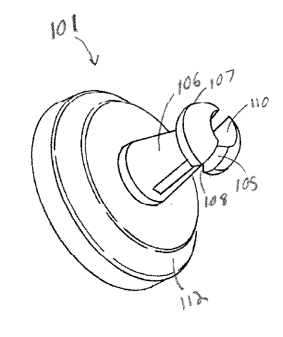
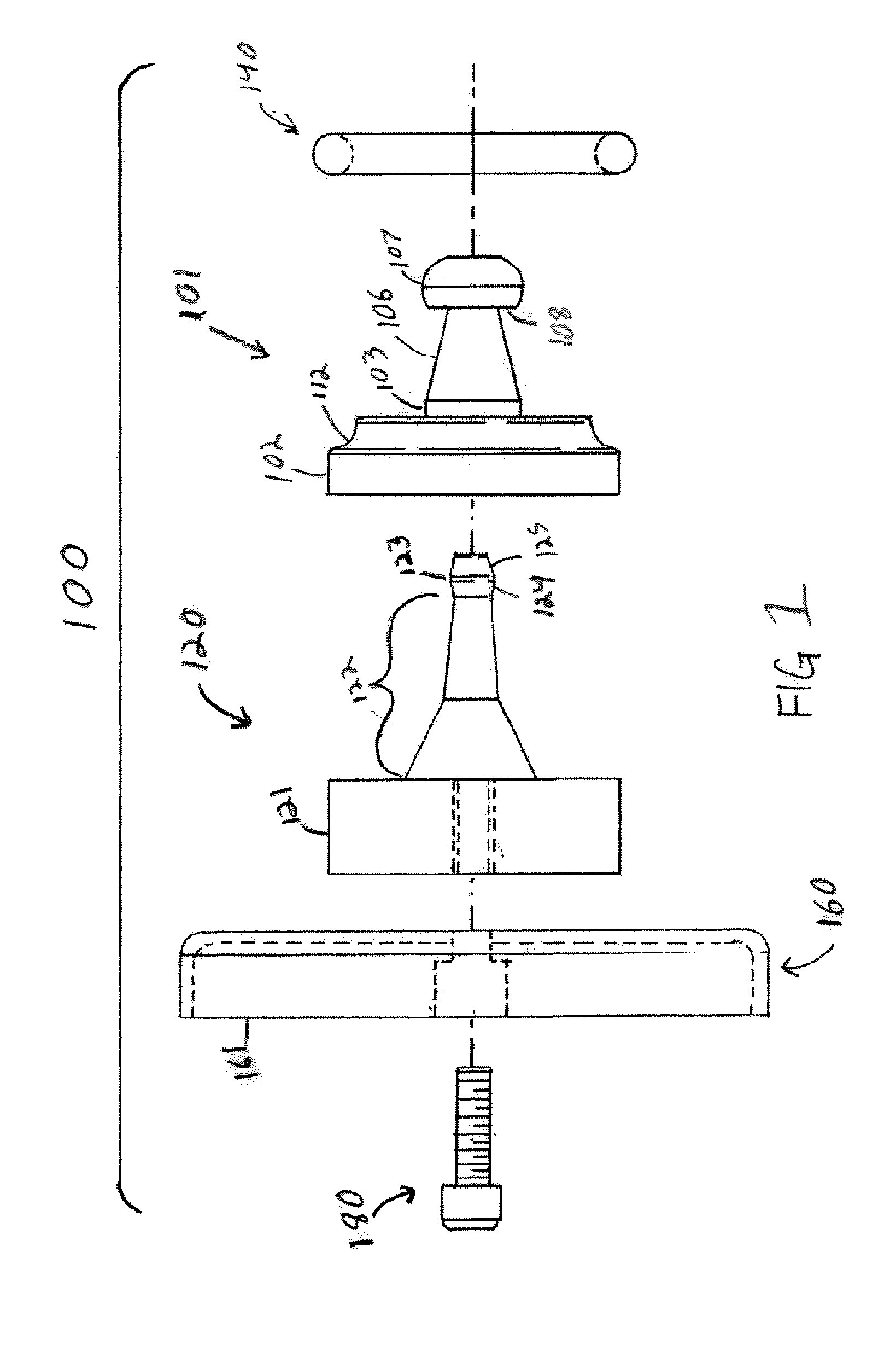
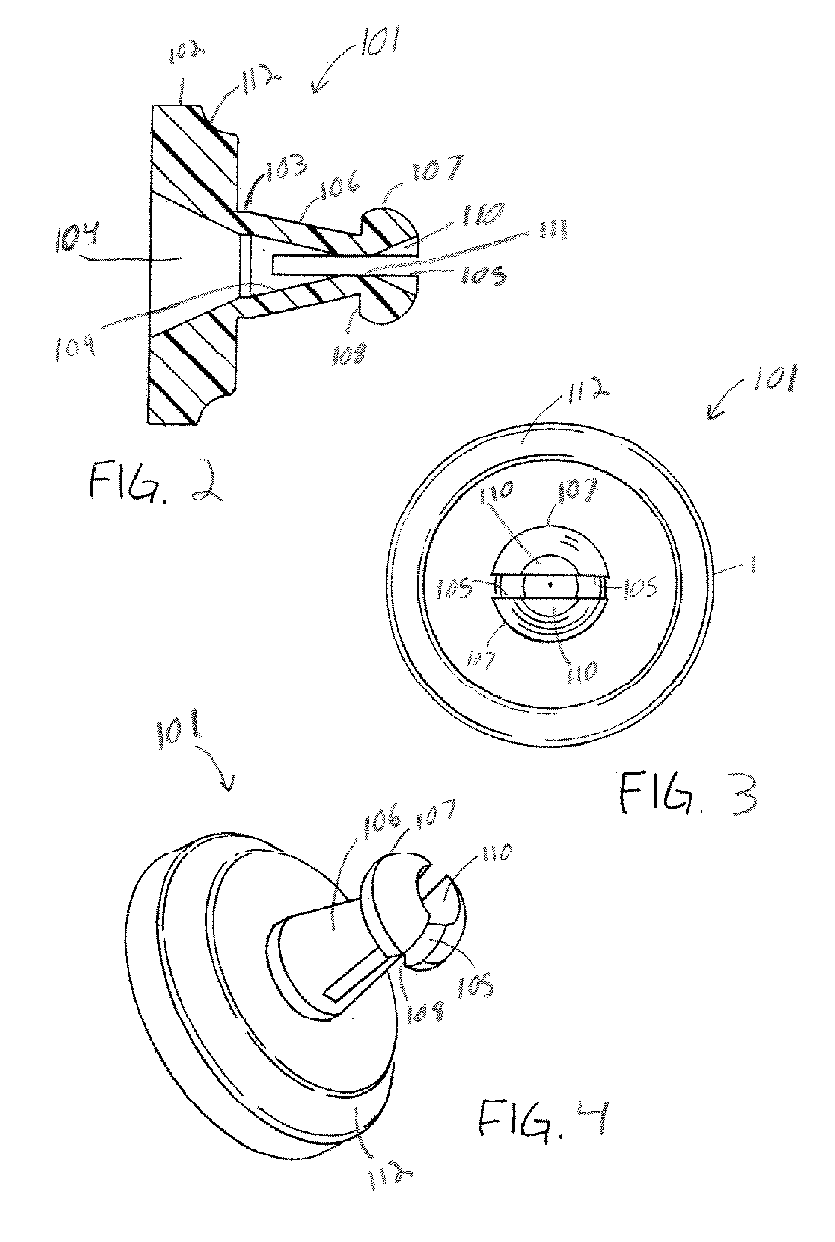
[0024]FIGS. 1-6 display the elements forming mounting apparatus 100. Mounting apparatus 100 comprises bushing 101 and plunger 120. Mounting apparatus 100 is used with a perforated board 200 having at least one hole 201, typically a plurality forming a pattern, that passes all the way through from a front surface 202 to a rear surface 203 of the board 200. Bushing 101 is inserted into a hole 201 in the board 200 and is locked in to the board 200 by receiving plunger 120 in a bore 104 that passes through the bushing 101.

[0025] Bushing 101 comprises a body portion 102 and sleeve 103. The body portion 102 comprises an outer perimeter that is greater than the size of the hole 201 in which the bushing 101 is to be mounted. Thus, when sleeve 103 is inserted in to the hole 201, a portion of body portion 102 is flush with the front surface 202 of the perforated board 200. Bushing 101 is moveable from: 1) a first position in which the outer surface of the sleeve 103 comprises a decreasing ou...


PUM


Abstract

A mounting apparatus for securing to a perforated surface, including a bushing having a body portion from which a sleeve extends for insertion into a perforation, and a bore which extends through both the body and sleeve. The mounting apparatus also has a plunger that includes a head from which a stud extends. The bushing of the mounting apparatus is moveable from a first position to a second position. In the first position the sleeve of the bushing has a decreasing outer perimeter. In the second position the sleeve of the bushing is inserted into a perforation and the sleeve is radially expanded engaging the perforation by inserting the stud of the plunger into the bore of the bushing. When in the second position the apparatus has a mounting surface which extends away from the mounting surface. The mounting apparatus can further include a holding element and a magnetic element.

Description

CROSS-REFERENCE TO RELATED APPLICATIONS [0001] This application claims priority benefits under 35 §U.S.C. 119(e) of the U.S. Provisional Application No. 60 / 830,523 filed on Jul. 13, 2006.FIELD OF THE INVENTION [0002] The present invention relates to fasteners used to mount items to a perforated surface. BACKGROUND OF THE INVENTION [0003] Fasteners are used to hold items on a perforated surface. The majority of fasteners sold comprise of hooks or loops (generally “hooks”) hanging off at least one hole in the surface. The way a hook is attached to the surface is usually via a bent rod which forms an offset portion at the top. This offset portion is inserted into the board using a rotating motion and once inserted the hook is allowed to hang from the hole, with the back of the hook resting upon the front surface of the wall. [0004] One problem with this type of hook is that when an item is placed on the hook all its weight is supported by the bottom of a hole the hook is inserted into....

Claims


Application Information

Patent Timeline
Patent Type & Authority Applications(United States)
IPC IPC(8): F16B13/04A47B96/06
CPCF16B13/063F16B2001/0035F16B13/126F16B2200/83
Inventor ZASLOFF, DAVID
Owner ZASLOFF DAVID
Why Eureka
Try Eureka