Supercharge Your Innovation With Domain-Expert AI Agents!

Method of making a compound magnet

a compound magnet and magnet technology, applied in the field of compound magnets, can solve the problems of significant time and effort, difficult to make a compound magnet, and difficult assembly

Inactive Publication Date: 2008-01-24
CREIGHTON IV FRANCIS M +1
View PDF5 Cites 44 Cited by
  • Summary
  • Abstract
  • Description
  • Claims
  • Application Information

AI Technical Summary

Benefits of technology

[0005] The present invention relates to improved methods and apparatus of making compound magnets that have a regions of different magnetization directions. Generally, a preferred embodiment of the method of this invention comprises assembling a plurality of sections of magnetizable material having a preferred direction of magnetization into a block. Each section corresponds to a region or a part of a region, and the preferr

Problems solved by technology

It would be difficult to make a compound magnet in which the magnetization direction varies from a monolithic block of magnetic material.
Assembly can be a difficult and time consuming procedure because the sections exert attractive and repulsive forces on each other, that increase as the section are brought together.
Significant time and effort is spent placing each section, and the difficulty actually increases as the assembly of the block progresses.

Method used


Image

  • Method of making a compound magnet
  • Method of making a compound magnet
  • Method of making a compound magnet

Examples


Embodiment Construction

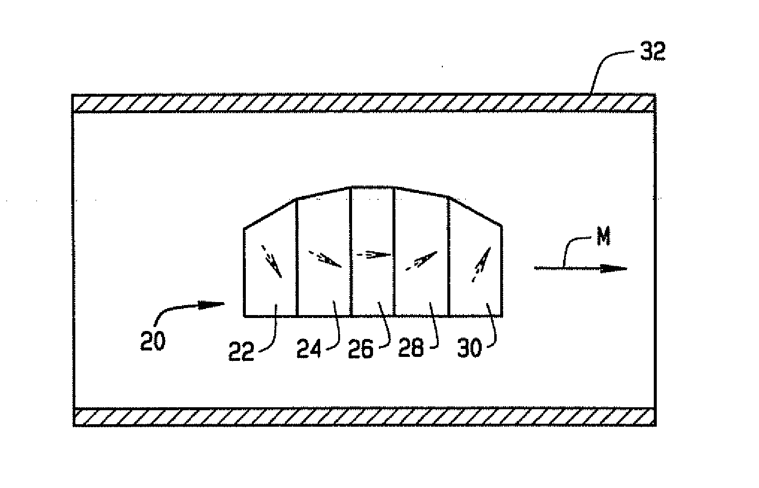
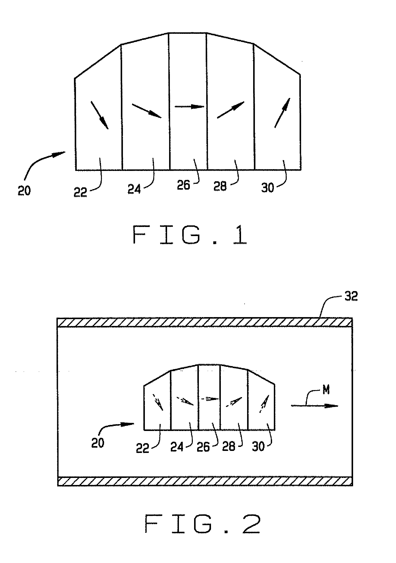
[0032] This invention relates to a method of making compound magnets, such as magnet 20, which comprises five regions 22, 24, 26, 28 and 30, at least some of which have different magnetization directions indicated generally by solid headed arrows. Because of the varying magnetization directions of each of the five regions, the magnet 20 has enhanced magnetic properties compared to a magnet of similar size and shape, which is magnetized in a uniform direction. For example, the magnet 20 may be designed and constructed to optimize the magnetic field in a particular direction F, at a point spaced from the magnet for use in a magnetic navigation system. Of course the magnet 20 could be optimized for any other magnetic property, if desired, for this or other applications.

[0033] Prior to this invention, the magnet 20 would be formed by making sections each corresponding to a region or a portion of a region, and gluing the sections together. However because of the varying magnetization di...


PUM

PropertyMeasurementUnit
Angleaaaaaaaaaa
Angleaaaaaaaaaa
Forceaaaaaaaaaa

Abstract

A method of making a compound magnet that comprises a plurality of regions at least some of which have different magnetization directions. The method comprises assembling a plurality of sections of magnetizable material having a preferred direction of magnetization into a block, each section corresponding to a region or a part of a region, and the preferred magnetization direction of each section being aligned with the desired magnetization direction of its corresponding region. The sections in the assembled block are magnetized to form the compound magnet.

Description

CROSS-REFERENCE TO RELATED APPLICATIONS [0001] This application claims priority to U.S. Provisional Patent Application No. 60 / 424,498, filed Nov. 7, 2002, the disclosure of which is incorporated herein by reference.BACKGROUND OF THE INVENTION [0002] This invention relates to compound magnets, and in particular to a method of making compound magnets. [0003] A compound magnet is a magnet that has a plurality of regions at least some of which have different magnetization directions. This allows the magnet to have “focused” or improved properties over a magnet in which the magnetization is uniform. For example the magnetic field at a given point can be optimized, so that the compound magnet achieves a greater field strength than a conventional magnet, or at least achieves a greater strength per unit volume. Compound magnets have a number of applications, for example in magnetic surgery systems where one or more magnets is used to create a magnetic field inside the operating region in a ...

Claims


Application Information

Patent Timeline
IPC IPC(8): H01F7/00H01F7/06H01F13/00H01F41/02
CPCH01F13/003H01F41/0273Y10T29/49075Y10T29/49014Y10T29/49073
Inventor CREIGHTON, IV, FRANCIS M.WERP, PETER R.
Owner CREIGHTON IV FRANCIS M
Features
  • R&D
  • Intellectual Property
  • Life Sciences
  • Materials
  • Tech Scout
  • Unparalleled Data Quality
  • Higher Quality Content
  • 60% Fewer Hallucinations
Learn More