Seal and window clamp assembly

Inactive Publication Date: 2008-01-24
ARVINMERITOR TECH
View PDF10 Cites 0 Cited by
  • Summary
  • Abstract
  • Description
  • Claims
  • Application Information

AI Technical Summary

Benefits of technology

[0008]The subject invention provides a snap-in seal that is easily secured to a window clamp without an adhesive, and which does not detach from the window clamp during loading and unloading

Problems solved by technology

The application of an adhesive increases c

Method used


Image

  • Seal and window clamp assembly
  • Seal and window clamp assembly
  • Seal and window clamp assembly

Examples


Example

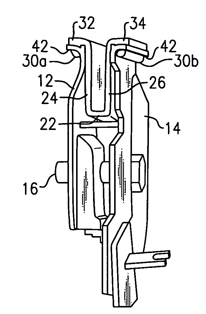
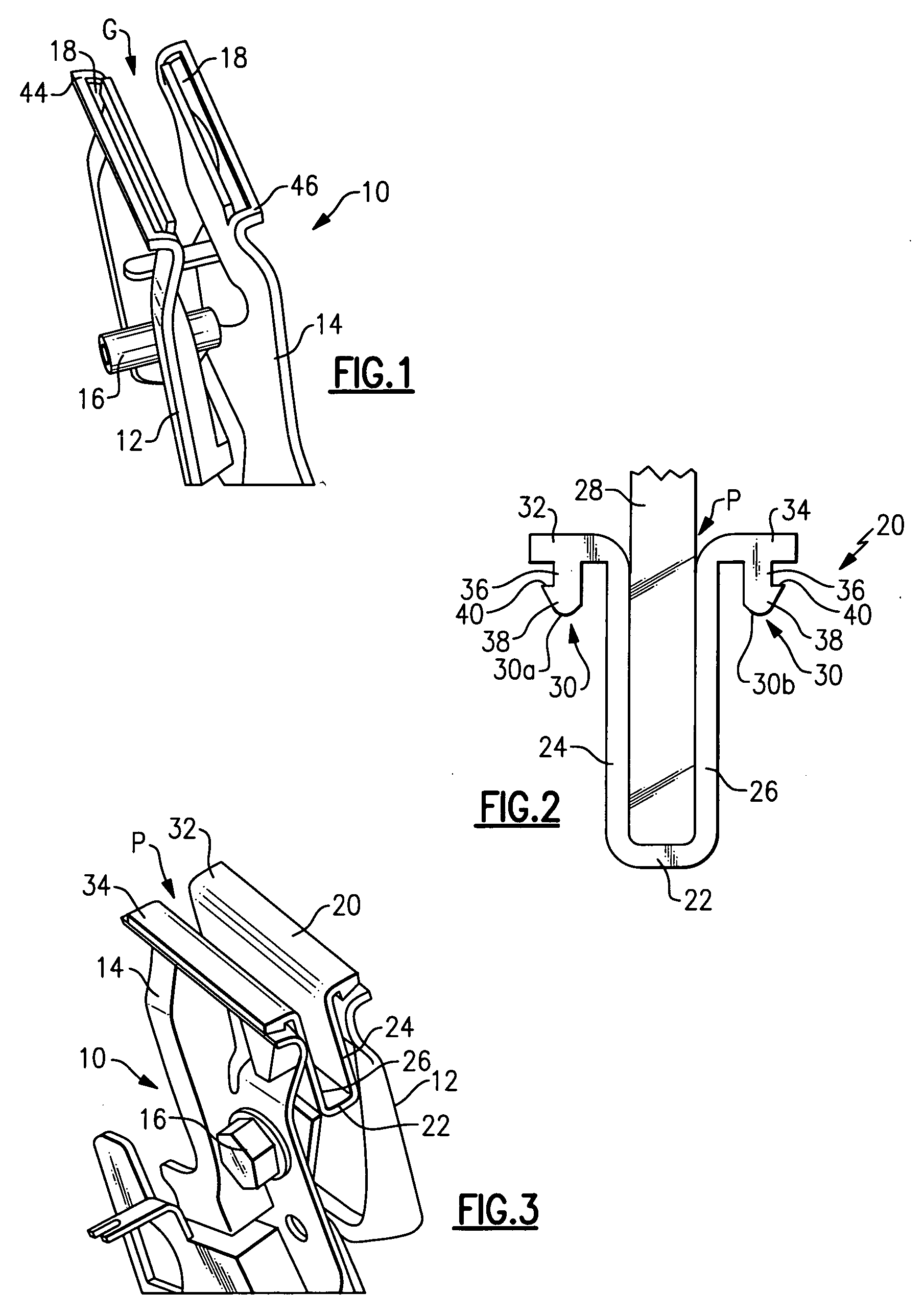
[0016]FIG. 1 shows an example of a window clamp 10 that includes a first clamp arm 12 and a second clamp arm 14. Lower portions of the first 12 and second 14 clamp arms are secured together with at least one fastener 16 as known. Upper portions of the first 12 and second 14 clamp arms are spaced apart from each other to provide a gap G. Each of the first 12 and second 14 clamp arms includes a slot 18.

[0017]A seal 20, shown in FIG. 2, is inserted into the gap G. The seal 20 is an extruded single-piece member that is cut to a desired length. The seal 20 can be made out of any type of resilient seal material. The seal 20 includes a base portion 22 and first 24 and second 26 seal arms that extend upwardly from the base portion 22. Upper portions of the first 24 and second 26 seal arms are spaced apart from each other to form a pocket P that receives a vehicle window 28. The first 24 and second 26 seal arms directly engage and seal against opposing sides of the vehicle window 28, i.e. bo...


PUM


Abstract

A window clamp is used to hold a vehicle window within a vehicle door. The window clamp includes first and second clamp arms that are secured together with a fastener. A seal is inserted into a gap between first and second clamp arms. The seal includes first and second seal arms that engage both side surfaces of the vehicle window. The first and second clamp arms each include a slot. Portions of the seal are snapped into each slot to secure the seal to the window clamp.

Description

TECHNICAL FIELD[0001]The subject invention relates to a seal and clamp assembly for holding a window in a vehicle door.BACKGROUND OF THE INVENTION[0002]A window is moved between open and closed positions by a window regulator assembly that is mounted to a door module. The window is supported within a vehicle door by a clamp. The clamp is operably coupled to a movable component of the window regulator assembly. The clamp securely holds the window in place as the window regulator assembly moves the window between open and closed positions.[0003]The clamp includes a pair of clamp arms that are separated from each other by a gap. A seal is received within this gap. The seal has a pair of seal arms that are connected to each other at a base portion and are separated from each other by an opening at their distal ends. An edge of the window is inserted into this opening and the clamp arms and seal arms grip opposing sides, i.e. both surfaces, of the window to hold the window in place.[0004...

Claims


Application Information

Patent Timeline
IPC IPC(8): E05F11/38
CPCE05F11/385E05Y2900/55E05Y2600/53
Inventor RAMANAN, BALAJIJAIN, ANIL
Owner ARVINMERITOR TECH
Why Eureka
Try Eureka