Parabolic reflector protective insert

a technology of parabolic reflectors and protective inserts, which is applied in the direction of instruments, lighting and heating equipment, transportation and packaging, etc., can solve the problems of high cost and high specialized of specially designed lighting elements or globes capable of producing such light, and the risk of damage is greatly increased, so as to facilitate the secure and protect the globe, the effect of quick and easy transportation

Inactive Publication Date: 2007-05-03
PROFILE ILLUMINATION
View PDF22 Cites 0 Cited by
  • Summary
  • Abstract
  • Description
  • Claims
  • Application Information

AI Technical Summary

Benefits of technology

[0007] The present invention provides a more efficient manner of protecting globes within a light housing. Specifically, the present invention allows a user to easily secure and protect a globe used in the television and motion picture industry so as to allow for a quick and easy transport of the supporting lighting apparatus.

Problems solved by technology

Specially designed lighting elements or globes capable of producing such light are very expensive and highly specialized.
Although such globes provide the desired non-flickering light source, such globes are delicate and easily subject to damage.
While the globe and supporting light housing are stationary, the risk of damage is less, however, when the movement of the light is required, which may be often in on location shoots, the risk of damage is greatly increased.
The delicate nature and high cost of the globes makes their transportation a very man hour intensive and time consuming process.
If left inside the supporting housing, the globe may crack, due to forces associated with transportation which will permanently damage the globe.
Removing the globe from the housing is a delicate procedure that usually requires two specially trained lighting technicians.
As can be appreciated movement of such lights is very tedious, time consuming and expensive.
Additionally, the removal procedure also contributes to globes breakage requiring expensive replacement, despite the extra care and protection.

Method used


Image

  • Parabolic reflector protective insert
  • Parabolic reflector protective insert
  • Parabolic reflector protective insert

Examples


Embodiment Construction

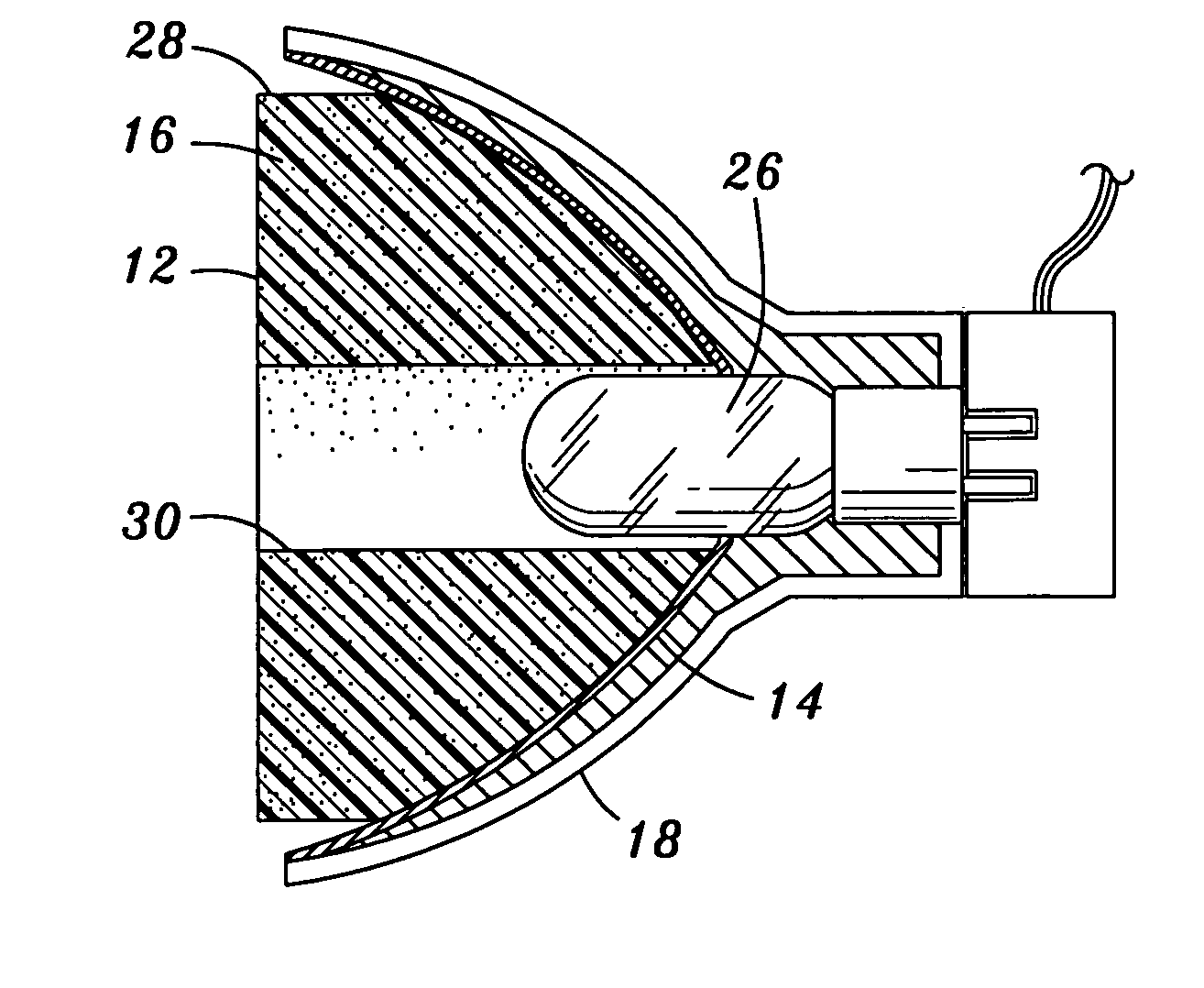
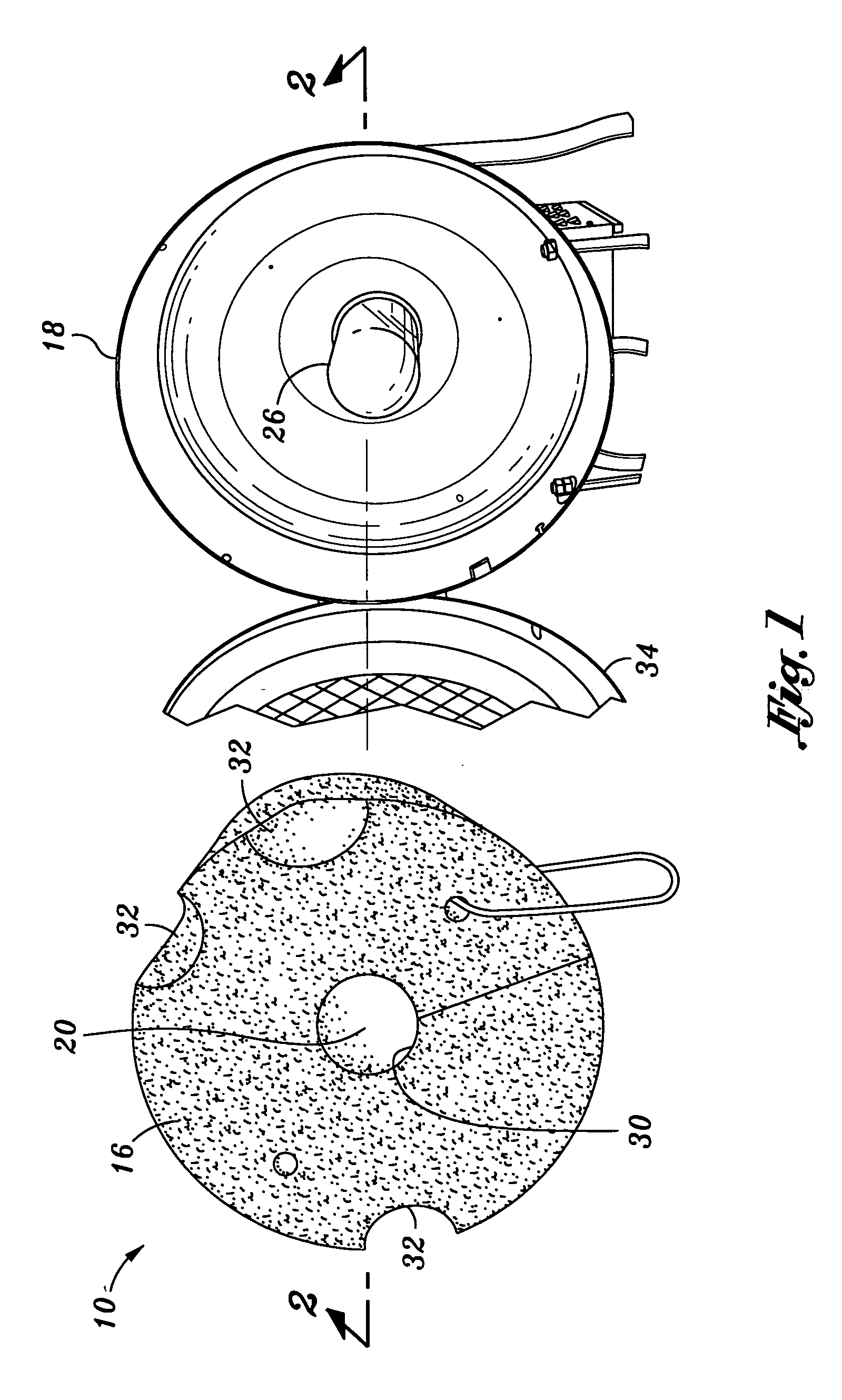
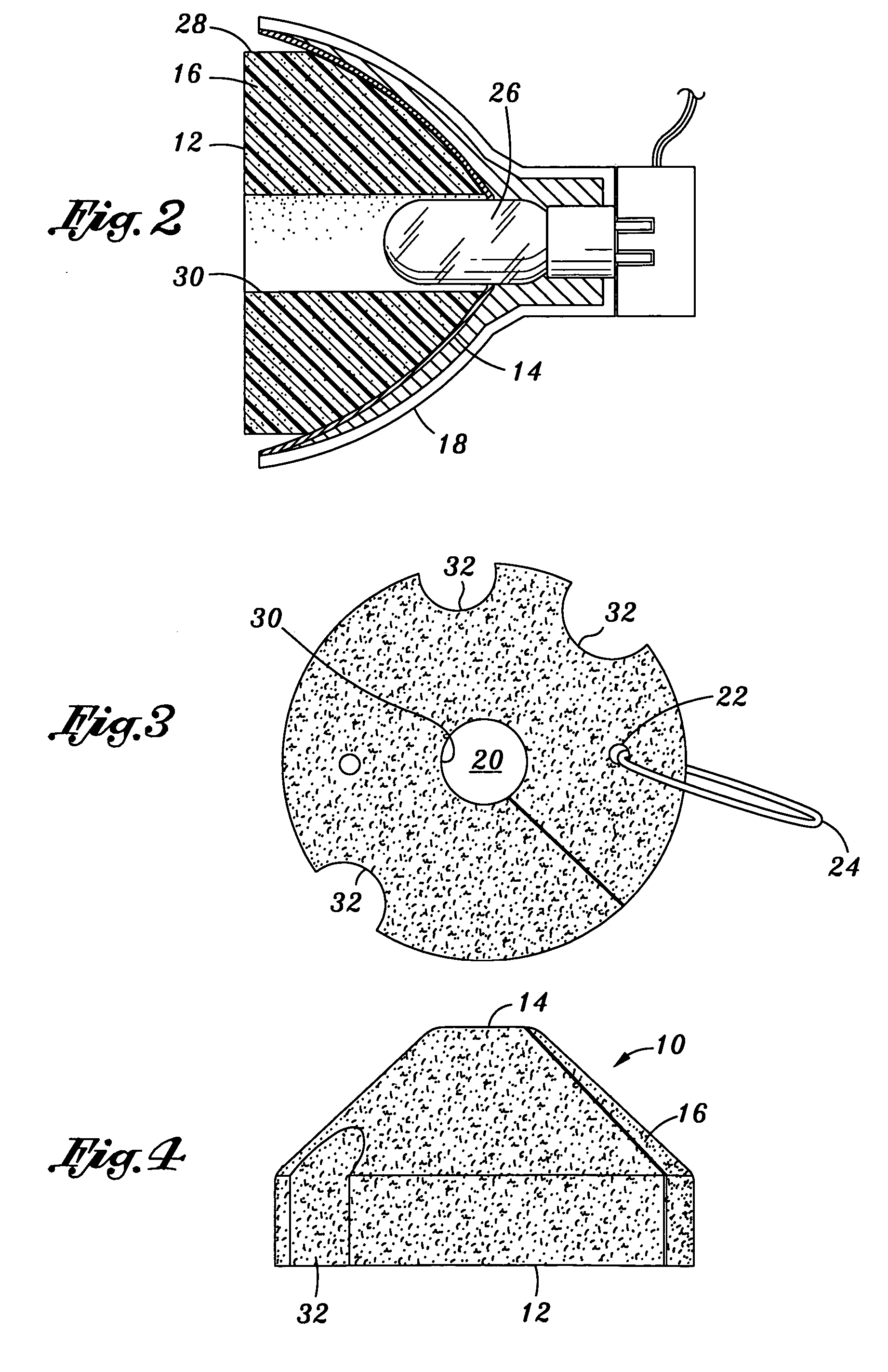
[0016] Referring now to the drawings wherein the showings are for purposes of illustrating preferred embodiments of the present invention only, and not for purposes of limiting the same, FIGS. 1-4 illustrate a protective insert 10 constructed in accordance with the present invention. The insert 10 is intended to be placed within a light housing 18 having a globe 26 in order to protect the globe 26 during transport or storage. For purposes of this disclosure, the term “globe” means any species of lighting elements used with motion picture or television filming, or any other light element that might be protected by use of the device of the present invention. The invention is intended to be utilized on globes 26 commonly used in television and motion picture lighting applications.

[0017] The insert 10 comprises a resilient body 16 which is configured to fit in place when inserted within the light housing 18. The insert 10 has an upper surface 12 and a lower surface 14 and is sized such...


PUM


Abstract

The present invention involves a method and apparatus of protecting a lighting element within a parabolic reflective housing. The apparatus involves a lighting element-protective member for use in within a light reflector housing cavity wherein lighting element protrudes into the cavity. A resilient body is provided and is selectively deformable to be frictionally engaged with the inner surface of the reflector housing. An aperture is formed in the resilient body for receiving the lighting element within said aperture. Thus the lighting element is protected within a foam sleeve which abuts the sides of the parabolic reflector for support. Also, method of protecting the lighting element is disclosed comprising the steps of: providing a selectively deformable resilient body; providing an aperture within the resilient body; and inserting the resilient body within the reflector such that the aperture receives and covers the lighting element.

Description

CROSS-REFERENCE TO RELATED APPLICATIONS [0001] Not Applicable STATEMENT RE: FEDERALLY SPONSORED RESEARCH / DEVELOPMENT [0002] Not Applicable BACKGROUND OF THE INVENTION [0003] The present invention relates to securing and protecting lighting elements within reflective light housings. More particularly, the present invention is used in television and motion picture lighting applications wherein a foam body is inserted into parabolic reflectors to envelope and support the fragile globes and thereby protect the globes within the parabolic reflectors when the light is not in use. [0004] The filming of motion pictures or television shows requires a constant light source with no flickering. Specially designed lighting elements or globes capable of producing such light are very expensive and highly specialized. Each globe may cost thousands of dollars, and some globes have been known to operate at temperatures as high as 600-800° C. (about 1100-1500° F.) (see Malek et al., U.S. Pat. No. 5,09...

Claims


Application Information

Patent Timeline
Patent Type & Authority Applications(United States)
IPC IPC(8): B65D81/02
CPCB65D81/1075B65D81/113
Inventor WALKER, PHILIP
Owner PROFILE ILLUMINATION
Why Eureka
Try Eureka