Printing apparatus and head maintenance method in printing apparatus

a printing apparatus and maintenance method technology, applied in printing, power drive mechanisms, spacing mechanisms, etc., can solve problems such as wiring system layout and piping system, and achieve the effect of reliably preventing pipe breakage and the like during the collective movement of printing bar units and easily and reliably ensuring the security

Pending Publication Date: 2022-08-18
DAINIPPON SCREEN MTG CO LTD
View PDF1 Cites 0 Cited by
  • Summary
  • Abstract
  • Description
  • Claims
  • Application Information

AI Technical Summary

Benefits of technology

[0005]This invention was developed in view of the above problem and aims to easily and reliably secure a work space for allowing an operator to access printing bar units in a printing apparatus for printing an image by discharging inks different from each other to a printing medium from a plurality of the printing bar units arrayed adjacently.
[0008]In the invention thus configured, the pipes and the wires are connected to each printing bar unit. Those printing bar units arranged adjacent to each other are collectively moved in parallel to the second horizontal direction. Accordingly, the pipes and the wires also move according to the movements of the printing bar units to the maintenance space. However, depending on a layout state of the pipes and the wires, not only the pipes and the like may be broken during the movements, but also the work space may be limited by the presence of the pipes and the like. Accordingly, in the invention, the pipes and the like are guided in parallel to the second horizontal direction according to the collective movements of the printing bar units while being stored and protected by the protecting / guiding member arranged outside and adjacent to the body frame. In this way, the breakage of the pipes and the like during the collective movements of the printing bar units is reliably prevented. Moreover, the pipes and the like stored in the protecting / guiding member move outside the body frame and are not present inside the body frame. As a result, the work space can be secured without being limited by the collective movements of printing bar units to the maintenance space.
[0009]As described above, according to the invention, a work space for allowing an operator to access discharge heads can be easily and reliably secured in a printing apparatus for printing an image by discharging inks different from each other to a printing medium from a plurality of printing bar units arrayed adjacently.

Problems solved by technology

However, the layouts of a piping system and a wiring system are not considered at all in JP 2017-177362A.

Method used


Image

  • Printing apparatus and head maintenance method in printing apparatus
  • Printing apparatus and head maintenance method in printing apparatus
  • Printing apparatus and head maintenance method in printing apparatus

Examples


Embodiment Construction

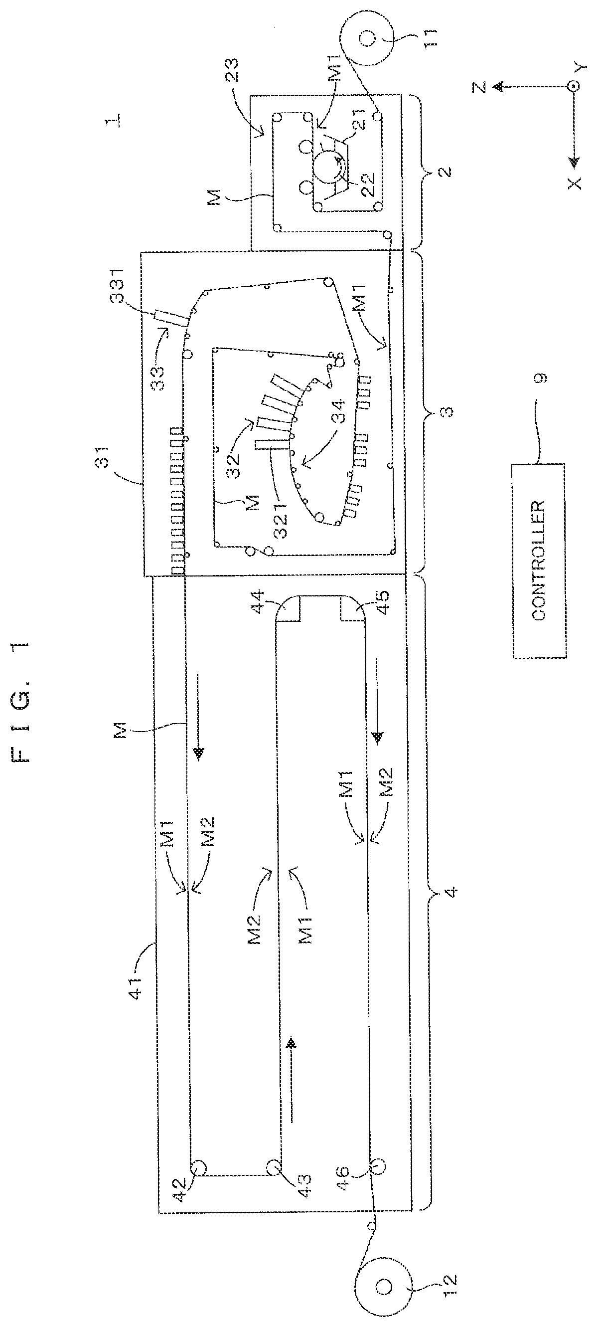
[0017]FIG. 1 is a front view schematically showing an example of a printing system equipped with one embodiment of a printing apparatus according to the invention. In FIG. 1 and subsequent figures, a horizontal direction in which a coating apparatus 2, a printing apparatus 3 and a drying apparatus 4 constituting a printing system 1 are arranged is referred to as an “X direction”, a horizontal direction from a right side toward a left side of FIG. 1 is referred to as a “+X direction” and an opposite direction is referred to as a “−X direction” to clarify an arrangement relationship of each component of the apparatus. Further, out of horizontal directions Y orthogonal to the X direction, a direction forward of the apparatuses is referred to as a “+Y direction” and a direction backward of the apparatuses is referred to as a “−Y direction”. Further, upward and downward directions along a vertical direction Z are respectively referred to as a “+Z direction” and a “−Z direction”.

[0018]Thi...


PUM


Abstract

In the invention, pipes and the like are guided in parallel to a second horizontal direction according to collective movements of printing bar units while being stored and protected by a protecting / guiding member arranged outside and adjacent to a body frame. In this way, breakage of the pipes and the like during the collective movements of printing bar units is reliably prevented. Moreover, the pipes and the like stored in the protecting / guiding member move outside the body frame and are not present inside the body frame. As a result, a work space can be secured without being limited by the collective movements of the printing bar units to the maintenance space.

Description

CROSS REFERENCE TO RELATED APPLICATION[0001]The disclosure of Japanese Patent Application No. 2021-023141 filed on Feb. 17, 2021 including specification, drawings and claims is incorporated herein by reference in its entirety.BACKGROUND OF THE INVENTION1. Field of Invention[0002]This invention relates to a printing apparatus for printing an image by discharging inks different from each other to a printing medium from a plurality of printing bar units arrayed adjacently and a method for maintaining the printing bar units in the printing apparatus.2. Description of the Related Art[0003]A printing apparatus is known which prints an image on the upper surface of a printing medium by discharging a water-based or oil-based ink or the like to the printing medium by an inkjet method from discharge heads provided in a printing bar unit. For example, in a printing apparatus described in JP 2017-177362A, a plurality of printing bar units are arrayed along a conveying direction of a printing me...

Claims


Application Information

Patent Timeline
Patent Type & Authority Applications(United States)
IPC IPC(8): B41J25/34
CPCB41J25/34B41J2/16588B41J19/005B41J29/02B41J29/377B41J2/175
Inventor UMAKOSHI, SHOICHIASADA, KAZUHIKO
Owner DAINIPPON SCREEN MTG CO LTD
Why Eureka
Try Eureka