
Paint can holder

a paint can and can holder technology, applied in the field of paint can holders, can solve the problems of difficulty in accessing the paint can, and difficulty in painting while on a ladder

Inactive Publication Date: 2008-01-24
GM GLOBAL TECH OPERATIONS LLC +1
View PDF11 Cites 8 Cited by
  • Summary
  • Abstract
  • Description
  • Claims
  • Application Information

AI Technical Summary

Problems solved by technology

Painting whilst on a ladder presents difficulties.
Specifically, the painter needs one hand for the paint brush and, if the other needs to hold the paint can, the painter's balance is precarious.
However, accessing the paint can may be difficult.

Method used


Image

  • Paint can holder
  • Paint can holder

Examples


Embodiment Construction

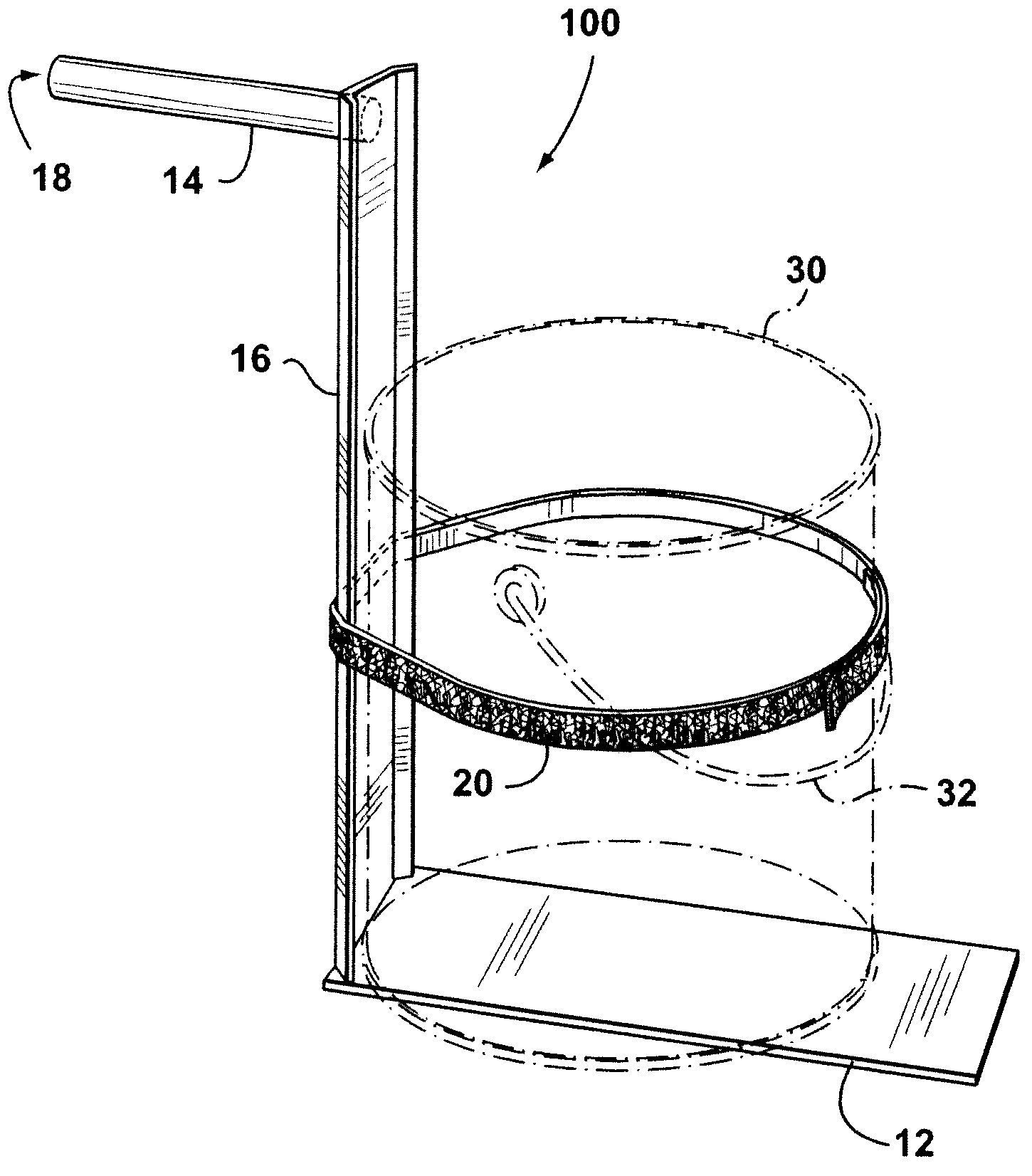
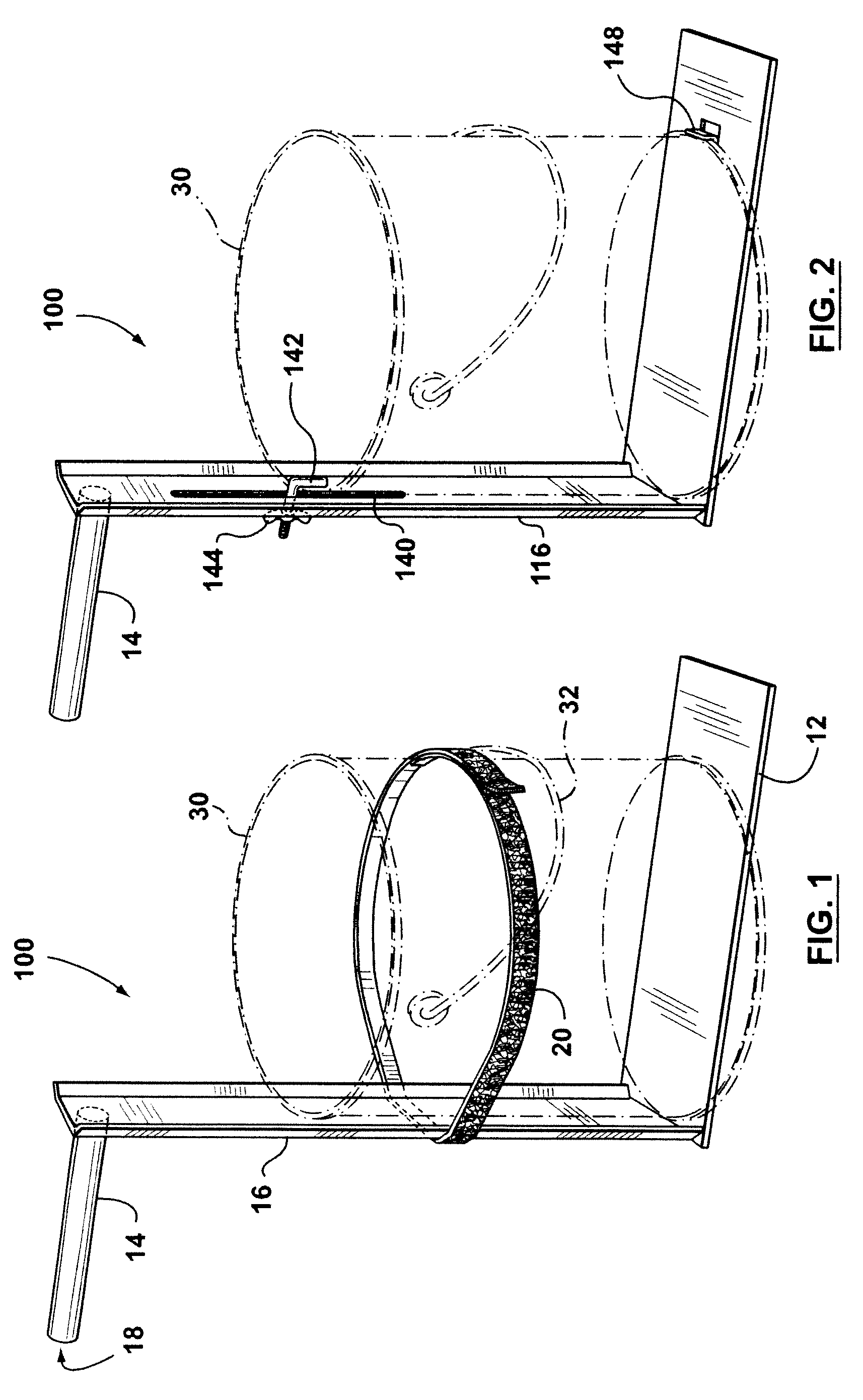
[0009]Turning to FIG. 1, a paint can holder 10 may have a paint can support with a lower paint can platform 12 and a web 16. The holder may also have an upper rod-like projection 14 which is parallel to the platform but projects in the opposite direction to the platform. The web 16 may interconnect the platform and rod-like projection. The platform, web, and rod-like projection may present a generally Z-shaped profile. The rod-like projection may be cylindrical in shape and has a free end 18. A mechanism, such as strap 20 tethered to the vertical web 16, may be provided to hold the paint can to the support. Each end of the strap 20 may be provided with one of hooks and loops of a hook and loop fastening system. Apart from the strap, the holder may be made from metal, or plastic.

[0010]As seen in FIG. 1, a paint can 30 may be set atop the platform 12 and then the strap 20 brought around the circumference of the can underneath the can handle 32 and the ends of the strap joined with the...


PUM


Abstract

A paint can holder has a paint can support and a rod-like projection projecting from the support away from any paint can supported by the paint can support. The rod-like projection has a free end remote from the support. The rod-like projection is configured such that the rod-like projection may be inserted into a rung of a ladder to support the paint can from the ladder.

Description

BACKGROUND[0001]Painting whilst on a ladder presents difficulties. Specifically, the painter needs one hand for the paint brush and, if the other needs to hold the paint can, the painter's balance is precarious.[0002]Canadian patent no. 2,455,919 discloses a paint can holder to which a paint can may be attached. The holder has two parallel hooks which allow the holder to be hung from a rung of a ladder. This allows the painter to use the ladder to hold the paint can. However, accessing the paint can may be difficult.[0003]Therefore a need remains for an improved paint can holder.SUMMARY OF INVENTION[0004]A paint can holder has a paint can support and a rod-like projection projecting from the support away from any paint can supported by the paint can support. The rod-like projection has a free end remote from the support. The rod-like projection is configured such that the rod-like projection may be inserted into a rung of a ladder to support the paint can from the ladder.[0005]Other...

Claims


Application Information

Patent Timeline
IPC IPC(8): A47G29/02
CPCE06C7/143
Inventor ANDERSON, MARK
Owner GM GLOBAL TECH OPERATIONS LLC
Learn More