Side loaded valve assembly

a technology of exhaust valve and side load, which is applied in the direction of valve details, valve arrangements, machines/engines, etc., can solve the problems of generating a chattering noise of the flapper valve, difficult to efficiently package the exhaust valve components within the exhaust components, and durability issues of the bushings and associated exhaust valve components. achieve the effect of reducing valve chatter and simple and cost-effectiv

Active Publication Date: 2008-01-24
ET US HLDG
View PDF3 Cites 9 Cited by
  • Summary
  • Abstract
  • Description
  • Claims
  • Application Information

AI Technical Summary

Benefits of technology

[0010]In each of these examples, the side load feature provides a simple and cost-effective mechanism for side loading the shaft to reduce valve chatter. These

Problems solved by technology

When the flapper valve is in the closed position, there is a tendency for the flapper valve to generate a chattering noise, which is not desirable.
This movement generates the chattering noise and can also lead to durability issues for the bushings and associate

Method used


Image

  • Side loaded valve assembly
  • Side loaded valve assembly

Examples


Embodiment Construction

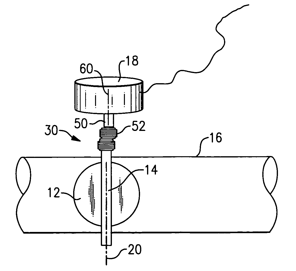
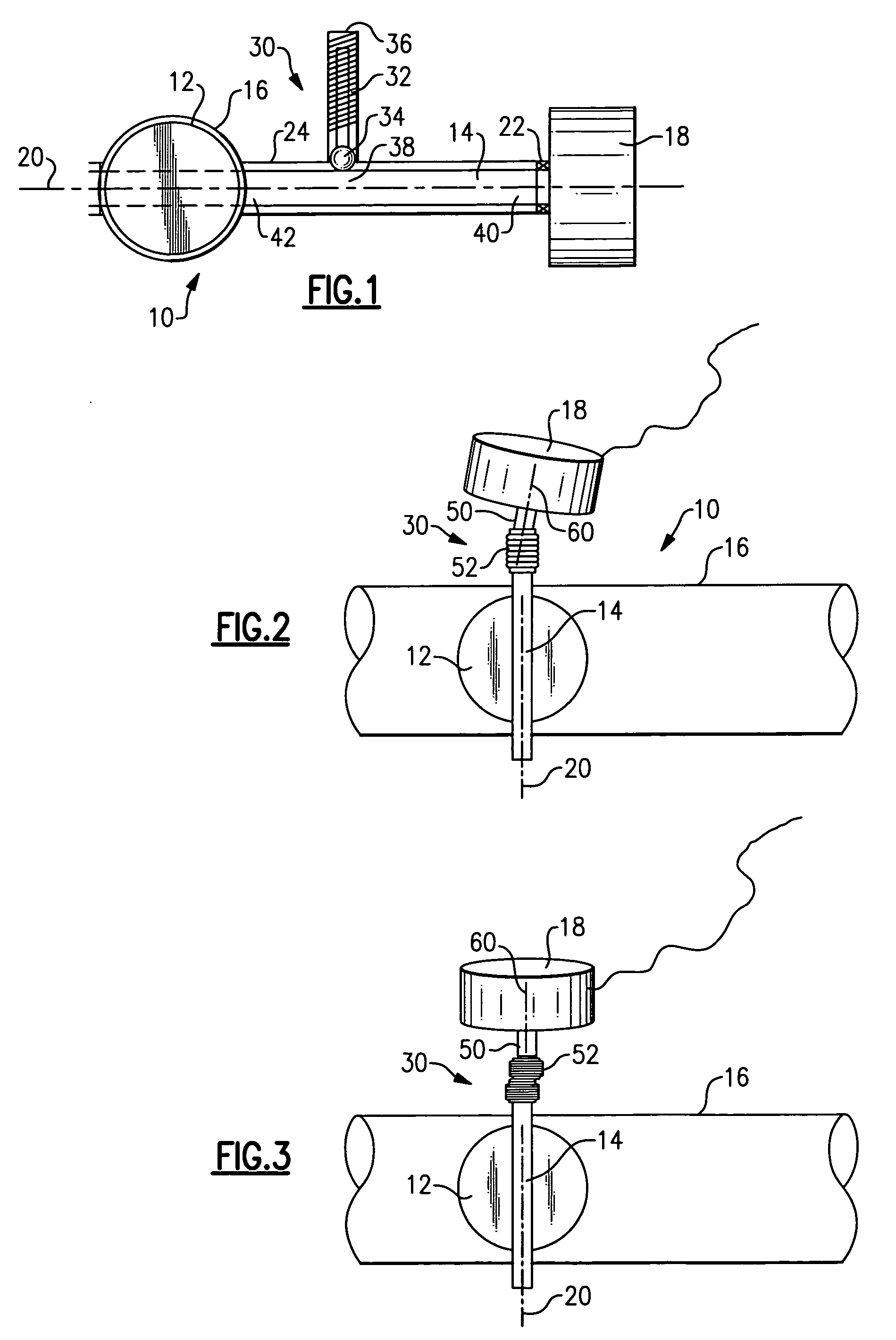
[0014]An exhaust valve assembly is shown generally at 10 in FIG. 1. The exhaust valve assembly 10 includes a valve 12 that is supported on a shaft 14. In the example shown, the valve 12 comprises a flapper valve that is mounted within a valve body 16, which comprises a tube. The valve body 16 is part of an exhaust system component and exhaust gases flow through the valve body 16.

[0015]An actuator 18 drives the shaft 14 to rotate about an axis 20 defined by the shaft 14. At least one bearing or bushing 22 supports the shaft 14 for rotation relative to a shaft housing 24. The shaft housing 24 is part of, or attached to, the valve body 16. The valve 12 is fixed to the shaft 14 such that the shaft 14 and valve 12 pivot about the axis 20 together. The actuator 18 can be any type of actuator including a spring actuator, an electric actuator such as a motor or solenoid, or a vacuum actuator, for example. The actuator 18 pivots the valve 12 between open and closed positions to control exhau...


PUM


Abstract

An exhaust valve assembly includes a valve body, a valve supported by a shaft within the valve body, and an actuator that drives the shaft to move the valve relative to the valve body. A side load feature engages one portion of the shaft to reduce valve chatter by side loading the shaft.

Description

TECHNICAL FIELD[0001]The subject invention relates an exhaust valve assembly with a side loaded shaft that provides reduced valve chatter.BACKGROUND OF THE INVENTION[0002]Exhaust valve assemblies include a flapper valve that is supported on a shaft within an exhaust tube. An actuator drives the shaft to move the flapper valve within the exhaust tube to control exhaust flow. Actuators can include spring actuators, electric actuators such as motors or solenoids, or vacuum actuators, for example. The shaft is supported by bushings such that the shaft and flapper valve can pivot together about an axis.[0003]The actuator provides a driving output to the shaft to pivot the flapper valve between an open and closed position within the exhaust tube. When the flapper valve is in the closed position, there is a tendency for the flapper valve to generate a chattering noise, which is not desirable. This chattering behavior is a result of the movement of the flapper valve, driven by exhaust pulsa...

Claims


Application Information

Patent Timeline
IPC IPC(8): F16K31/44
CPCF02D9/04F16K35/04F16K1/50F16K1/221
Inventor CALLAHAN, JOSEPHABRAM, KWINARBUCKLE, IVANWILLATS, ROBIN
Owner ET US HLDG
Why Eureka
Try Eureka