
Flow stop valve

a technology of flow stop valve and stop valve, which is applied in the direction of fluid removal, earthwork drilling and mining, and well accessories, etc., can solve the problems of difficult to ensure, severely limited successive section depth, and significant increase in time and cost to drill to a certain depth, so as to reduce valve chatter

Active Publication Date: 2016-05-24
PILOT DRILLING CONTROL
View PDF138 Cites 2 Cited by
  • Summary
  • Abstract
  • Description
  • Claims
  • Application Information

AI Technical Summary

Benefits of technology

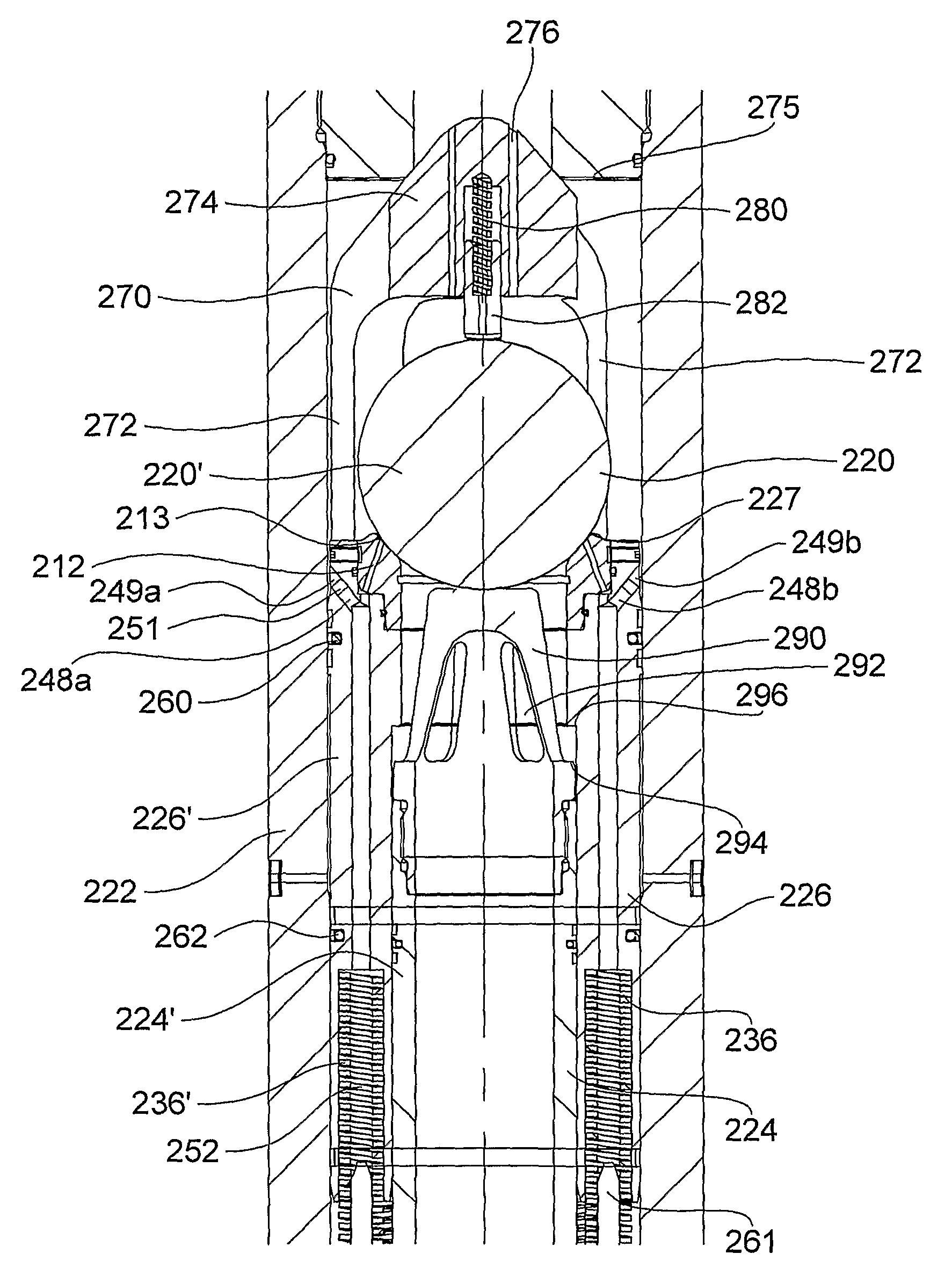
[0011]According to a first embodiment there is provided a flow stop valve for placement in a downhole tubular operating in a dual fluid density system, wherein the flow stop valve is arranged such that it is in communication with a pressure difference between: fluid outside the downhole tubular and inside the downhole tubular at the flow stop valve; or fluid above and below the flow stop valve inside the downhole tubular, wherein the flow stop valve comprises a first valve element arranged such that the pressure difference acts across at least a portion of the first valve element and that the first valve element is movable between open and closed positions under action of said pressure difference so as to selectively permit flow through the downhole tubular, wherein the first valve element comprises a first passage arranged so as to transmit fluid from a first port in a first side of the first valve element to a second side of the first valve element, the first port being positioned such that it is adjacent to a low pressure flow region when the flow stop valve is in an at least partially open position. The low pressure flow region may be in fluidic communication with the second side of the first valve element via the first port and the first passage. The flow stop valve may reduce valve chatter and / or may assist in opening the valve. For example, the flow stop valve may assist by opening the valve more quickly or opening the valve more fully than it would have otherwise.
[0024]According to another embodiment there is provided a method of controlling flow in a downhole tubular operating in a dual fluid density system, the method comprising: restricting flow through the downhole tubular by closing a flow stop valve when a pressure difference between: fluid outside the downhole tubular and inside the downhole tubular at the flow stop valve; or fluid above and below the flow stop valve inside the downhole tubular, is below a threshold value; and permitting flow through the downhole tubular by opening the flow stop valve when the pressure difference is above a threshold value, wherein the method further comprises transmitting fluid from a first port in a first side of a first valve element to a second side of the first valve element, the first port being positioned such that it is adjacent to a low pressure flow region when the flow stop valve is in an at least partially open position. The low pressure flow region may be in fluidic communication with the second side of the first valve element via the first port and the first passage. The flow stop valve may reduce valve chatter and / or may assist in fully opening the valve.
[0031]According to another example of the invention, there is provided a flow stop valve, the flow stop valve comprising a first valve element arranged such that a pressure difference acts across at least a portion of the first valve element and that the first valve element is movable between open and closed positions under action of said pressure difference so as to selectively permit flow through the downhole tubular, wherein the first valve element comprises a first passage to transmit fluid from a first port in a first side of the first valve element to a second side of the first valve element, the first port being positioned next to a narrowing in the flow path when the flow stop valve is at least partially in the open position such that a low pressure is transmitted via the first passage to the second side of the first valve element. The flow stop valve may be for use in a downhole tubular operating in a dual fluid density system. The flow stop valve may reduce valve chatter and / or may assist in fully opening the valve.
[0032]According to another example of the invention, there is provided a method of operating a flow stop valve, the method comprising: providing a first valve element arranged such that a pressure difference acts across at least a portion of the first valve element and that the first valve element is movable between open and closed positions under action of said pressure difference so as to selectively permit flow through the downhole tubular, transmitting fluid from a first port in a first side of the first valve element to a second side of the first valve element, the first port being positioned next to a narrowing in the flow path when the flow stop valve is at least partially in the open position such that a low pressure is transmitted via the first passage to the second side of the first valve element. The flow stop valve may be for use in a downhole tubular operating in a dual fluid density system. The flow stop valve may reduce valve chatter and / or may assist in fully opening the valve.
[0038]A third abutment surface may be provided at a first end of the hollow tubular section such that the third abutment surface may limit the travel of the sleeve in the direction toward the first end of the housing. A flange may be provided at the second end of the hollow tubular section. A second abutment surface may be provided at the second end of the housing such that the second abutment surface of the housing may abut the flange of the tubular section limiting the travel of the hollow tubular section in a second direction, the second direction being in a direction towards the second end of the housing.

Problems solved by technology

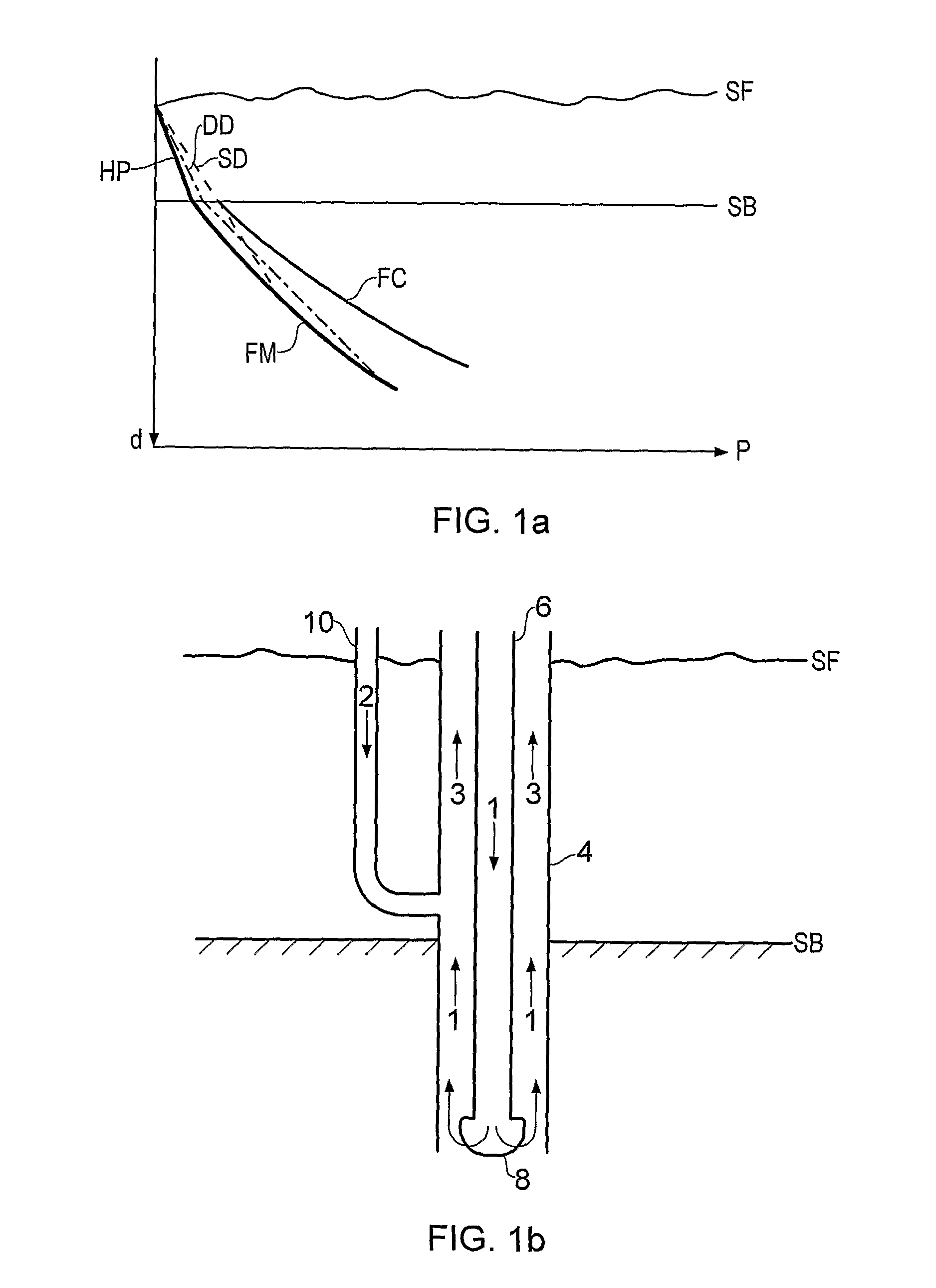
This change in pressure gradient makes it difficult to ensure that the pressure of the drilling fluid is between the formation and fracture pressures over a range of depths, because a single density SD drilling fluid does not exhibit this same step change in the pressure gradient.
However, the depths of successive sections are severely limited by the different pressure gradients, as shown by the single density SD curve in FIG. 1a, and the time and cost to drill to a certain depth are significantly increased.
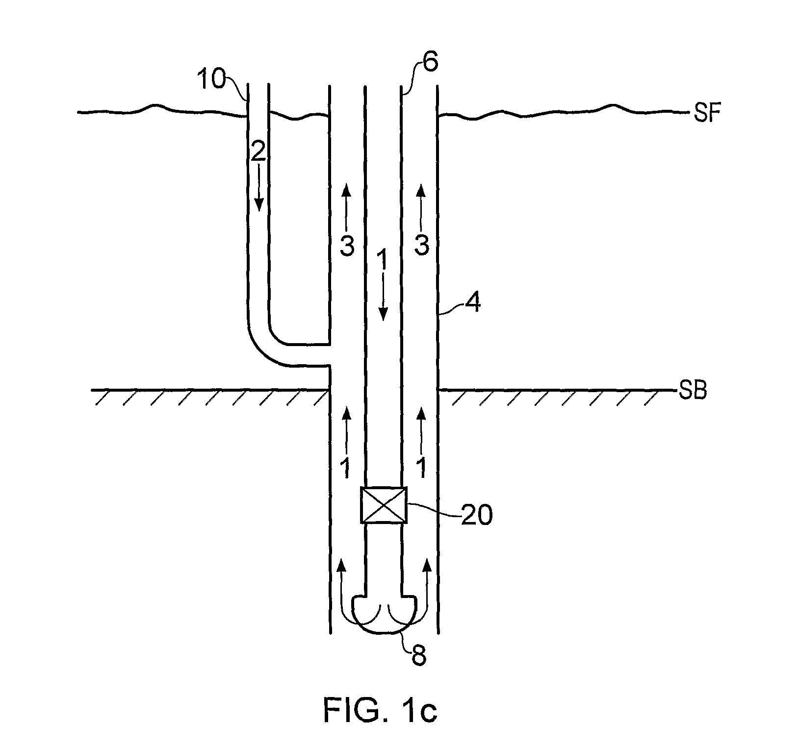
However, one problem with the proposed dual density systems is that when the flow of drilling fluid stops, there is an inherent hydrostatic pressure imbalance between the fluid in the tubular and the fluid outside the tubular, because the fluid within the tubular is a single density fluid which has a different hydrostatic head to the dual density fluid outside the tubular.
The same problem also applies when lowering casing sections into the well bore.
However, in some embodiments of such a valve, the valve may chatter when it is opened because once the flow stop valve has opened, the localised pressure above the valve reduces, thereby tending to close the valve again.

Method used


Image

  • Flow stop valve
  • Flow stop valve
  • Flow stop valve

Examples


first embodiment

[0114]With reference to FIG. 9, the flow stop valve 200 according to the present disclosure is suitable for placement in a downhole tubular operating in a dual fluid density system. (NB, FIG. 9 shows the flow stop valve in a closed position.) The flow stop valve 200 is arranged such that it is in communication with a pressure difference between one of: fluid outside the downhole tubular and inside the downhole tubular, e.g., at the flow stop valve; and fluid above and below the flow stop valve, e.g., either side of the flow stop valve 200 inside the downhole tubular. These pressure differences are substantially the same due to the density and hence the hydrostatic head of the fluid below the flow stop valve inside and outside the downhole tubular being the same. In the particular example shown in FIG. 9, the flow stop valve 200 is arranged such that it is in communication with a pressure difference between fluid outside the downhole tubular and inside the downhole tubular at the flo...

second embodiment

[0147]The flow stop valve 300 of the second embodiment comprises a first passage 312 provided in the sleeve 326. The first passage 312 may be arranged so as to transmit fluid from a first port 313 in the first end of the sleeve to the second end of the sleeve. In particular, the first port 313 may be positioned near to a neck or narrowing of the flow area between the first and second valve elements 326′, 320′ when the valve is in the open position. As a result, the first port 313 may be adjacent to a low pressure flow region when the flow stop valve 300 is in an open position due to the Venturi effect caused by the subsequent increase in flow velocities at the neck or narrowing.

[0148]The second embodiment otherwise functions in the same way as the first embodiment. In other words, the position at which further movement of the second valve element 320′ is prevented, e.g. by the spacer elements, determines the preload in resilient elements 336′ against which the pressure difference ac...


PUM


Abstract

A flow stop valve (200, 300, 400) for placement in a downhole tubular operating in a dual fluid density system, wherein the flow stop valve is arranged such that it is in communication with a pressure difference between one of: fluid outside the downhole tubular and inside the downhole tubular at the flow stop valve; and fluid above and below the flow stop valve inside the downhole tubular, wherein the flow stop valve comprises a first valve element (226′, 326′, 424) arranged such that the pressure difference acts across at least a portion of the first valve element and that the first valve element is movable between open and closed positions under action of said pressure difference so as to selectively permit flow through the downhole tubular, wherein the first valve element comprises a first passage (212, 312, 446) arranged so as to transmit fluid from a first port (213, 313, 447) in a first side of the first valve element to a second side of the first valve element, the first port being positioned such that it is adjacent to a low pressure flow region (290) when the flow stop valve is in an open position.

Description

[0001]This disclosure relates to a flow stop valve which may be positioned in a downhole tubular, and particularly relates to a flow stop valve for use in dual density drilling fluid systems.BACKGROUND[0002]When drilling a well bore, it is desirable for the pressure of the drilling fluid in the newly drilled well bore, where there is no casing, to be greater than the local pore pressure of the formation to avoid flow from, or collapse of, the well wall. Similarly, the pressure of the drilling fluid should be less than the fracture pressure of the well to avoid well fracture or excessive loss of drilling fluid into the formation. In conventional onshore (or shallow offshore) drilling applications, the density of the drilling fluid is selected to ensure that the pressure of the drilling fluid is between the local formation pore pressure and the fracture pressure limits over a wide range of depths. (The pressure of the drilling fluid largely comprises the hydrostatic pressure of the we...

Claims


Application Information

Patent Timeline
Patent Type & Authority Patents(United States)
IPC IPC(8): E21B21/10E21B21/00
CPCE21B21/10E21B2021/006E21B21/085
Inventor SWIETLIK, GEORGELARGE, ROBERTMORRIS, PETER RYAN
Owner PILOT DRILLING CONTROL
Learn More