
Imaging apparatus, imaging method, recording medium, and program

a technology of imaging apparatus and recording medium, applied in the direction of exposure control, optical radiation measurement, color signal processing circuit, etc., can solve the problems of difficult effective use of exposure time and unnatural image, and achieve the effect of flickering image during imaging by a video camera

Inactive Publication Date: 2008-01-24
SONY CORP
View PDF8 Cites 103 Cited by
  • Summary
  • Abstract
  • Description
  • Claims
  • Application Information

AI Technical Summary

Benefits of technology

[0013] When flicker is reduced by using frames having a phase difference of 180 degrees, an output image is the sum of two frames, so that the image is unnatural if the image includes a moving subject.
[0014] The present invention has been made in view of these circumstances and is directed to reducing flicker that occurs under a fluorescent-lighted environment during imaging performed by a video camera using an XY-address-scanning imaging device.
[0024] As described above, according to an embodiment of the present invention, flicker that occurs during imaging by a video camera or the like under a fluorescent-lighted environment can be reduced.
[0025] Also, according to an embodiment of the present invention, flicker that occurs during high-speed imaging by a video camera using an XY-address-scanning imaging device under a fluorescent-lighted environment can be reduced in accordance with shutter speed.

Problems solved by technology

However, when exposure time is used, the following problem arises.
Therefore, it is difficult to effectively use the exposure time.
When flicker is reduced by using frames having a phase difference of 180 degrees, an output image is the sum of two frames, so that the image is unnatural if the image includes a moving subject.

Method used


Image

  • Imaging apparatus, imaging method, recording medium, and program
  • Imaging apparatus, imaging method, recording medium, and program
  • Imaging apparatus, imaging method, recording medium, and program

Examples


Embodiment Construction

[0041] Before describing embodiments of the present invention, the correspondence between the features of the present invention and the specific elements disclosed in embodiments of the present invention is discussed below. This description is intended to assure that an embodiment supporting the present invention is described in this specification. Thus, even if an element in the following embodiments is not described as relating to a certain feature of the present invention, that does not necessarily mean that the element does not relate to that feature. Conversely, even if an element is described herein as relating to a certain feature, that does not necessarily mean that the element does not relate to other features.

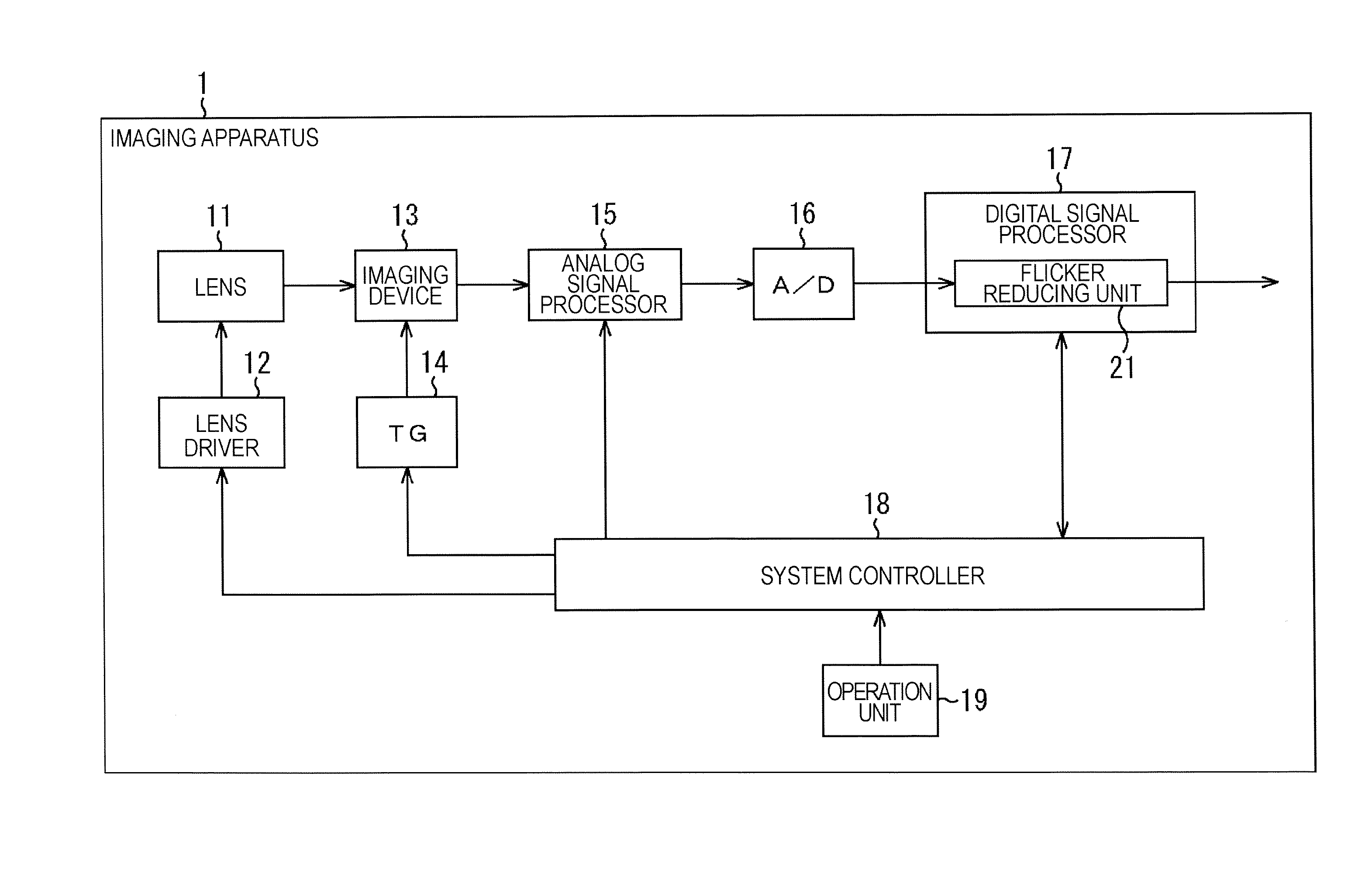
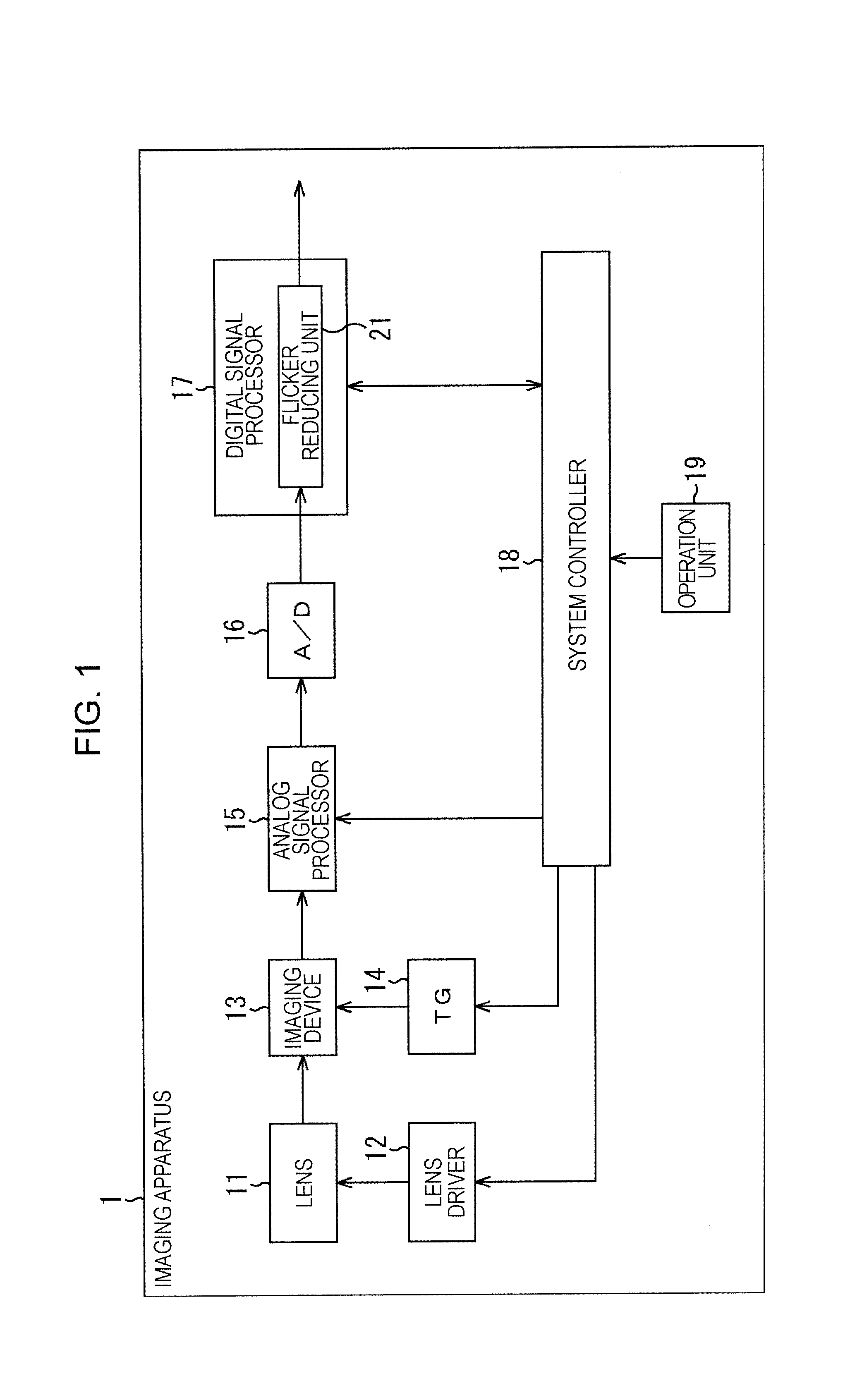
[0042] An imaging apparatus according to an embodiment of the present invention is an imaging apparatus including an XY-address-scanning imaging device (e.g., an imaging device 13 shown in FIG. 1) that performs imaging at a period of ½n (n is a natural number) of a l...


PUM


Abstract

An imaging apparatus includes an integrating unit to integrate pixel values of pixels in each of a plurality of areas of an image; a holding unit to hold integration values generated by the integrating unit; an operating unit to operate a waveform of a differential value between integration values of the same areas in two images having a phase difference of flicker of 180 degrees; an extracting unit to extract phase and amplitude of the flicker on the basis of the waveform operated by the operating unit; a selecting unit to select a waveform of the flicker on the basis of shutter speed of the imaging apparatus; and a correcting unit configured to correct the pixel values of the pixels by using a correction value based on the flicker waveform selected by the selecting unit and the phase and amplitude extracted by the extracting unit.

Description

CROSS REFERENCES TO RELATED APPLICATIONS [0001] The present invention contains subject matter related to Japanese Patent Application JP 2005-374957 filed in the Japanese Patent Office on Dec. 27, 2005, the entire contents of which are incorporated herein by reference. BACKGROUND OF THE INVENTION [0002] 1. Field of the Invention [0003] The present invention relates to an imaging apparatus, an imaging method, a recording medium, and a program. Particularly, the present invention relates to an imaging apparatus, an imaging method, a recording medium, and a program capable of reducing flicker that occurs during imaging performed by a video camera using an XY-address-scanning imaging device under a fluorescent-lighted environment. [0004] 2. Description of the Related Art [0005] As is conventionally known, flicker occurs due to fluorescent light during imaging of moving images performed by a video camera under a fluorescent-lighted environment. [0006] More specifically, when images of a s...

Claims


Application Information

Patent Timeline
Patent Type & Authority Applications(United States)
IPC IPC(8): H04N9/73G03B7/08G03B7/28H04N23/76H04N25/00
CPCH04N5/2357H04N5/235H04N23/70H04N23/745H04N23/76
Inventor KUSHIDA, HIDENORI
Owner SONY CORP
Learn More