Optical fiber mechanical splice connector

a technology of mechanical splicing and optical fiber, which is applied in the direction of optics, instruments, optical light guides, etc., can solve the problems of short changes in the length and bending characteristics of the fiber stub, and the proneness of long-term bending of the optical fiber, and achieve the effect of accurate alignment of the optical fiber and robust and reliable connectors

Active Publication Date: 2008-01-24
CORNING OPTICAL COMM LLC
View PDF24 Cites 38 Cited by
  • Summary
  • Abstract
  • Description
  • Claims
  • Application Information

AI Technical Summary

Benefits of technology

[0016] In one aspect, the present invention provides a robust and reliable connector for an optical fiber cut to length in the field. The optical fiber is cut to any length desired and the optical fiber is stripped of any protective layers along a short length at the end of the optical fiber. The optical fiber is inserted into the mechanical splice connector. An alignment mechanism ensures accurate alignment of the optical fiber with an internal fiber stub located within the optical connector.
[0018] In another aspect of an exemplary embodiment, the stub fiber of the optical connector is pre-selected to provide the necessary axial force when engaged with an inserted field fiber. The stub fiber preferably bends to the desired buckling radius without damage to the stub fiber. Optical fiber subject to long term bending may be prone to breakage due to critical flaw propagation. In order to minimize such breakage, either the critical flaw size due to surface damage is reduced or the stress due to bending is reduced below a critical level. In preferred embodiments, stripping methods which minimize surface damage should be employed. Toughened glass, such as fiber having a titania doped outer surface may be used to reduce the size of the flaws the fiber encounters during stripping. In another embodiment of the present invention, a stub fiber made from a plastic-clad 125 micron outer diameter optical fiber may be used. Plastic clad fiber has an enhanced ability to bend because the smaller glass outer diameter reduces the stress on the stub fiber while the plastic cladding prevents any surface damage to glass. Finally, a surface treatment, such as silane, may be applied to the fiber stub to make it more resistant to flaw propagation.
[0020] Yet another aspect of the present invention involves the tool used to install a field fiber within the connector of the present invention. The improved tool is closely related to the tool currently in use with a variety of mechanical splice connectors. The present invention improves on the prior art tool by incorporating the use of a sled structure for introducing the optical field fiber into the mechanical splice connector. The sled structure runs along a track designed within the installation tool. In an exemplary embodiment of the present invention, the sled structure also presents the optical fiber to the stripping and cleaving tools to accurately control the cleaving length and minimize errors due to handling. Therefore, a single device can be used to handle the fiber during cleaving, stripping, and installation of the fiber into the connector. After cleaving and stripping, the optical field fiber is still contained within the sled structure and placed within the track incorporated into the installation tool. The sled structure is then used to precisely guide the optical field fiber into the receiving end of the mechanical splice connector according to the present invention. When the optical field fiber exerts positive pressure onto the sled, the optical field fiber is in engagement with the fiber stub. The sled is then moved a predetermined distance further toward the mechanical splice connector. This forces the optical field fiber slightly further into the mechanical splice connector and causes the stub fiber contained within the optical connector to buckle controllably.

Problems solved by technology

Temperature differences may result in minute changes in the length and bending characteristics of the fiber stub and also the connector housing components.
Optical fiber subject to long term bending may be prone to breakage due to critical flaw propagation.

Method used


Image

  • Optical fiber mechanical splice connector
  • Optical fiber mechanical splice connector
  • Optical fiber mechanical splice connector

Examples


Embodiment Construction

[0031] Although the figures and following description are intended to provide a full disclosure of the present invention, including the preferred embodiment, such that a person of ordinary skill in the art may practice the invention, the embodiments shown and discussed subsequently are not intended to limit the scope of the present invention. The inventor contemplates that minor modifications and variations are within the scope of the present invention.

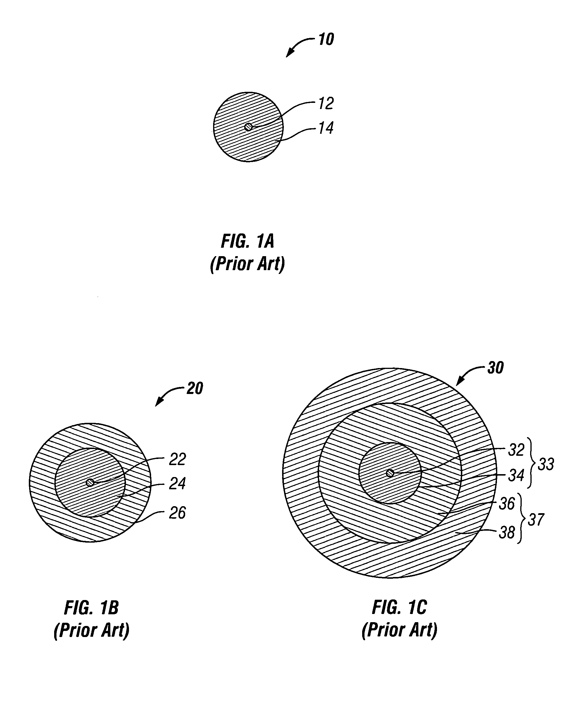
[0032] Referring now to FIGS. 1A-1C, three cross-sectional views of three different optical fibers are depicted. Each type of optical fiber may be relevant in the present invention. The figures are not to scale between one another nor is the relative thickness of each layer accurately portrayed. FIG. 1A depicts a typical optical fiber 10. The optical fiber 10 is comprised of a core 12 and a cladding 14. The core 12 and the cladding 14 are generally comprised of silica for optimum performance of the optical fiber. The cladding 14 feat...


PUM


Abstract

An optical fiber mechanical splice connector including a connector body having a fiber alignment mechanism and a cavity, and a ferrule including a stub fiber, wherein an end of the stub fiber extends from the ferrule through the cavity of the connector body and into the fiber alignment mechanism, and wherein the stub fiber buckles within the cavity when a field fiber is introduced into the connector body and contacts the distal end of the stub fiber. A mechanical splicing method including inserting a field fiber into a splice connector such that an end of the field fiber contacts an end of the stub fiber within an alignment mechanism of the splice connector, and applying axial force to the field fiber so as to cause the stub fiber to buckle within a cavity defined by the splice connector.

Description

BACKGROUND OF THE INVENTION [0001] 1. Field of the Invention [0002] The present invention relates generally to improved fiber optic connectors and, more specifically, to mechanical splice connectors that do not require the use of an index matching gel. [0003] 2. Technical Background [0004] Optical fibers are widely used in a variety of applications, including the telecommunications industry in which optical fibers are employed in a number of telephone and data transmission applications. Due, at least in part to the extremely wide bandwidth and the low noise operation provided by optical fibers, the use of optical fibers and the variety of applications in which optical fibers are used are continuing to increase. For example, optical fibers no longer serve as merely a medium for long distance signal transmission, but are being increasingly routed directly to the home, or in some instances, directly to a desk or other work location. [0005] With the ever increasing and varied use of opt...

Claims


Application Information

Patent Timeline
Patent Type & Authority Applications(United States)
IPC IPC(8): G02B6/255
CPCG02B6/3846G02B6/2558
Inventor DEJONG, MICHAEL
Owner CORNING OPTICAL COMM LLC
Why Eureka
Try Eureka