Portable Fluid Warming System

a fluid warming and portable technology, applied in the field of portable fluid warming systems, can solve the problems of induced hypothermia, hypothermia in trauma patients, and loss of efficiency of several relevant enzyme systems, and achieve the effects of reducing the risk of stroke, and reducing the survival rate of stroke victims

Active Publication Date: 2008-01-24
BOARD OF RGT THE UNIV OF TEXAS SYST
View PDF36 Cites 6 Cited by
  • Summary
  • Abstract
  • Description
  • Claims
  • Application Information

AI Technical Summary

Benefits of technology

[0015] Apparatus embodiments of the present invention are directed toward a portable biocompatible fluid warming system that may be used for infusing biocompatible liquids into a patient for the treatment of trauma. Various embodiments of the invention use heat from hydrocarbon combustion. Hydrocarbon combustion can take place in the absence of an open flame. As an example, in one embodiment, the present invention may be used with a gaseous hydrocarbon such as butane which is allowed to flow onto a platinum mesh and then ignited. The butane combines with oxygen and liberates heat which then heats the platinum mesh. In this embodiment, the temperature of the mesh stabilizes at the ignition temperature of the butane, thereby allowing combustion to occur on the surface of the platinum mesh.

Problems solved by technology

Several relevant enzyme systems begin to lose efficiency as their ambient temperature falls.
While profound hypothermia may be tolerated by immersion or cardiac surgery patients, the presence of hypothermia in trauma patients predicts significantly higher mortality.
The administration of fluid at ambient temperature, however, induces hypothermia.
This condition is worse in more severely injured patients, who require the most fluid and have the least ability to tolerate the additional insult of decreased core temperature.
Hypothermia and mortality clearly increase after the administration of five liters of crystalloid or five units of packed red blood cells, and the onset of hypothermia increases the incidence of coagulopathy in injured patients, particularly in the presence of acidosis.
This significantly limits the locations where the units may be used.
Locations such as non-industrialized nations or battlefield locations are likely not to have readily available sources of alternating current to power such systems.
The size and weight of such a unit would limit its portability.

Method used


Image

  • Portable Fluid Warming System
  • Portable Fluid Warming System
  • Portable Fluid Warming System

Examples


Embodiment Construction

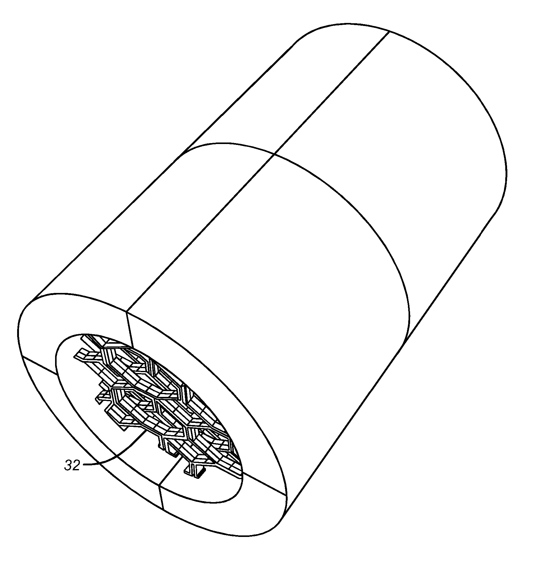
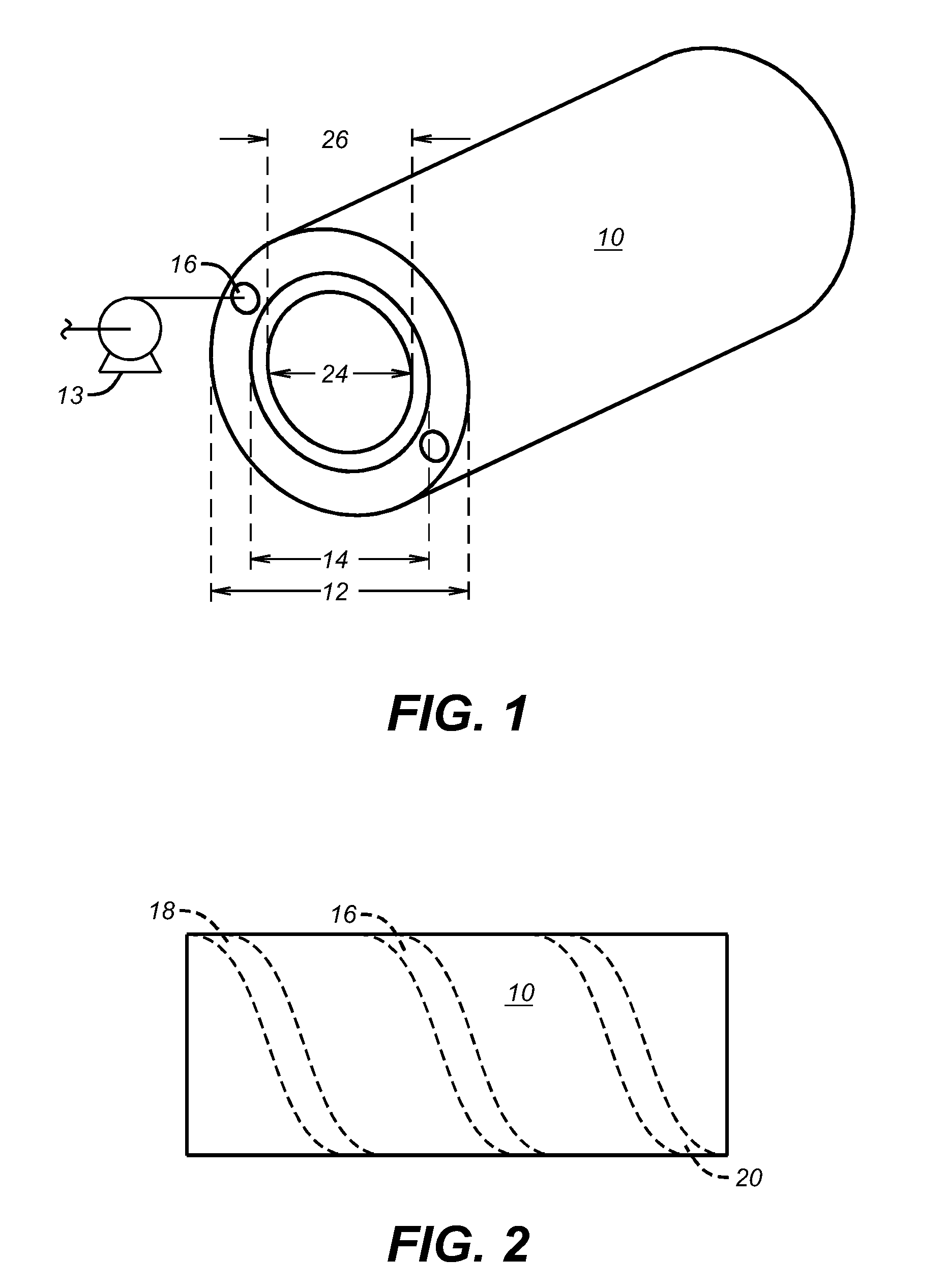
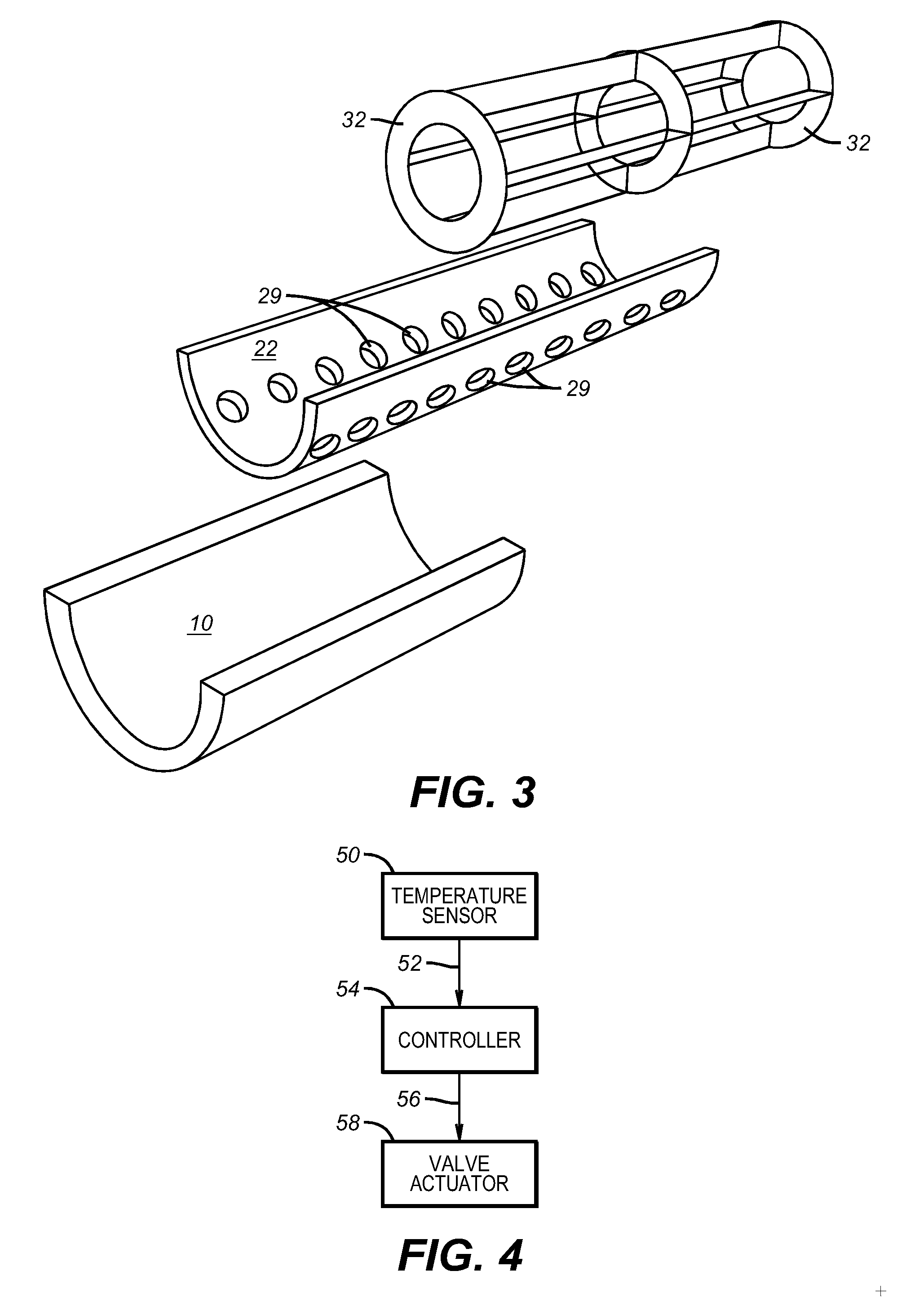
[0028] In a preferred embodiment, the present invention is directed toward a portable warmer of a biocompatible fluid comprising an outer housing 10 comprising a first outer diameter 12, a first inner diameter 14, and at least one flow channel 16 located between the first inner diameter and the first outer diameter as shown in FIGS. 2 and 3. In various preferred embodiments, the outer housing may comprise biocompatible material, including a biocompatible coating. The biocompatible material may be plastic or metal, including stainless steel. The portable warmer is a portable heat exchanger.

[0029] The term “diameter” as used herein refers to the length of an axis which bisects a cross sectional area of the housing. For cylindrical geometries the diameter is constant at a given point along the longitudinal axis of the cylindrical housing at various azimuths. For non-cylindrical geometries the diameter at a given point along the longitudinal axis of the housing may vary as a function o...


PUM


Abstract

The present invention relates to a portable apparatus for warming biocompatible fluids for use in the treatment of injured patients and a method of heating a biocompatible fluid to treat a patient experiencing hypothermia. The present invention may be used to warm intravenous fluids for trauma resuscitation or to warm air from a ventilator circuit. The portable nature of the present invention makes it highly suitable for field applications, such as a forward surgical hospital near a combat zone.

Description

CROSS REFERENCE TO RELATED APPLICATIONS [0001] This application is a continuation in part of application Ser. No. 10 / 886,191, filed on Jul. 7, 2004.BACKGROUND OF THE INVENTION [0002] 1. Field of the Invention [0003] The present invention relates to a portable apparatus for warming biocompatible fluids for use in the treatment of injured patients and a method of heating a biocompatible fluid to treat a patient experiencing hypothermia. The present invention may be used to warm intravenous fluids for trauma resuscitation or to warm air from a ventilator circuit. The portable nature of the present invention makes it highly suitable for field applications, such as a forward surgical hospital near a combat zone. [0004] 2. Description of the Prior Art [0005] Hypothermia is quite common in injured patients, including patients experiencing trauma. Hypothermia produces a number of physiologic derangements which worsen the effects of major injury. Several relevant enzyme systems begin to lose...

Claims


Application Information

Patent Timeline
Patent Type & Authority Applications(United States)
IPC IPC(8): A61F7/12A61F7/00F23D14/62
CPCA61F7/0085
Inventor GILL, BRIJESHCOX, CHARLES
Owner BOARD OF RGT THE UNIV OF TEXAS SYST
Why Eureka
Try Eureka