Implantable Medical Device Communication System

a communication system and medical device technology, applied in the field of medical device communication systems, can solve the problems of limiting the portability and mobility of the programmer, inconvenient wire connection, and affecting the portability of the programmer

Inactive Publication Date: 2008-01-24
CARDIAC PACEMAKERS INC
View PDF21 Cites 151 Cited by
  • Summary
  • Abstract
  • Description
  • Claims
  • Application Information

AI Technical Summary

Benefits of technology

[0016]The invention may be more completely understood by considering the detailed description of various embodiments of the invention that follows in connection with the accompanying drawings.

Problems solved by technology

However, a wired connection is often inconvenient, because the wire can get caught on equipment or interfere with the movement of people and other equipment in the vicinity.
The wire may also become tangled and limits the portability and mobility of the programmer.
An additional consideration associated with the transmission of information from a device implanted within a patient's body is the potential for interference with the signal.
These environments tend to be prone to interference as a consequence of the number of other wireless signals being transmitted in the same or adjacent frequency bands.
There is also a concern regarding the incompatibility of the available frequencies from one country to the next.
Furthermore, some countries may not have frequency bands allocated for medical telemetry at all.
These differences in allocated frequency bands render a device used in one geographic location incompatible for use in another geographic location.
The incompatibility of frequencies creates a risk that a patient who has traveled from one country to another will not receive the medical therapy or device programming that is required, and also creates difficulties for manufacturers of medical communication systems who have to design different devices for each geographic region rather than offering a product that can work anywhere.
Furthermore, some patients may be located in areas where traditional means of communication, such as by telephone or over the Internet, are not available.
In a crowded medical environment, however, the line of sight may be degraded due to the locations of people and objects.

Method used


Image

  • Implantable Medical Device Communication System
  • Implantable Medical Device Communication System
  • Implantable Medical Device Communication System

Examples


Embodiment Construction

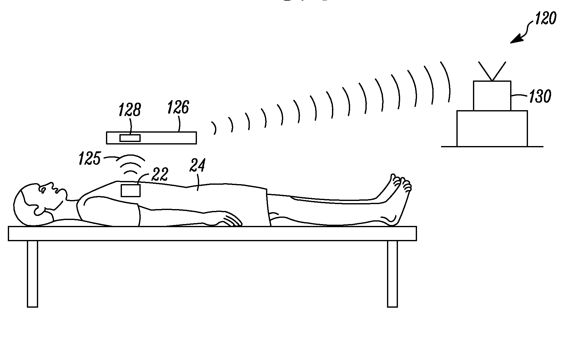
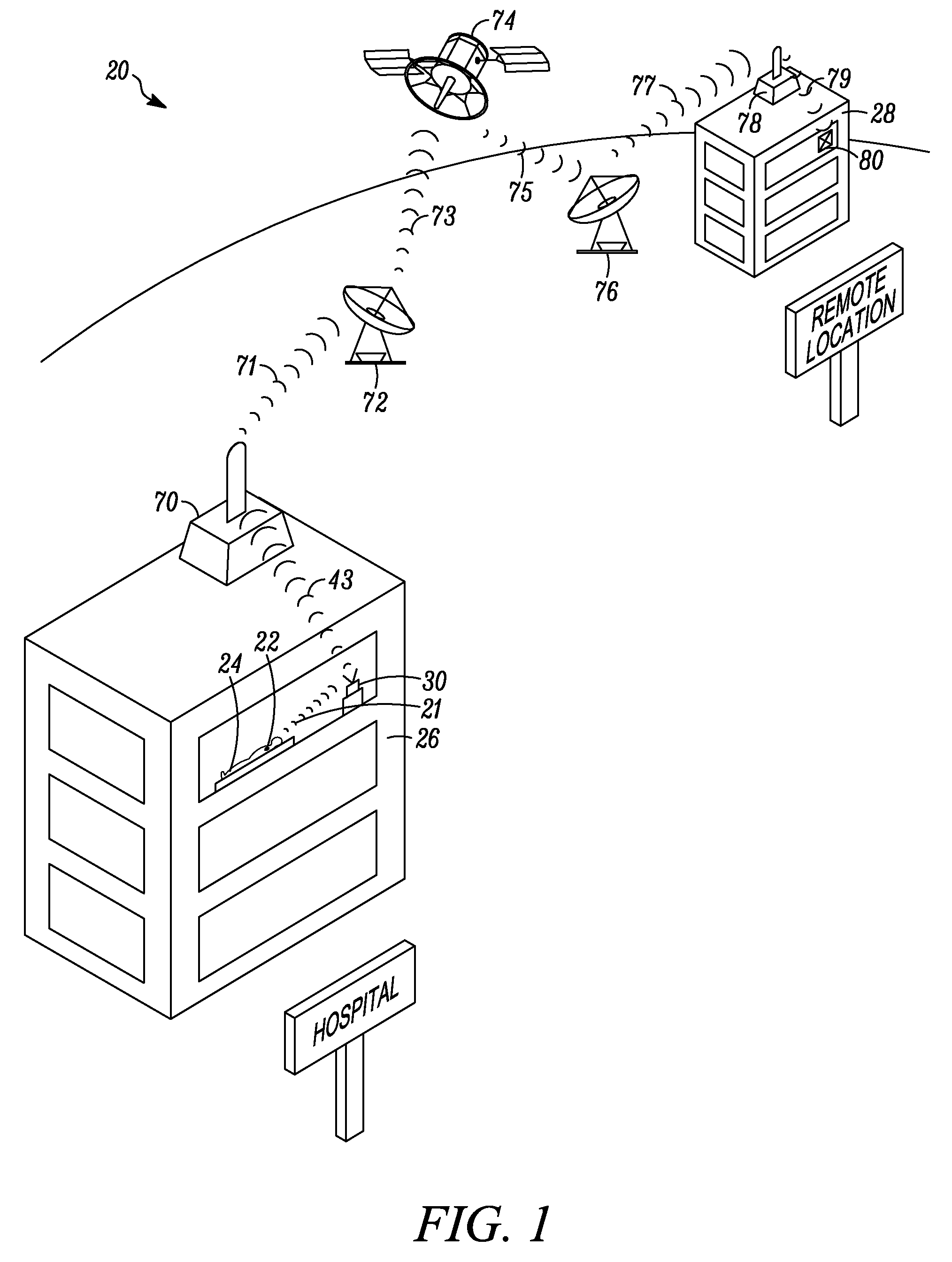
[0031]An embodiment of the invention is depicted in FIG. 1. Medical device communication system 20 is configured to transmit a signal having encoded information from an active implanted medical device (AIMD) 22 that is in a patient 24 who is in a medical facility 26 to a remote location 28. In the embodiment of FIG. 1, AIMD 22 communicates by a telemetric signal 21 to a programmer / recorder / monitor (PRM) 30 that is located within range of the transmission signal 21 from the AIMD 22. An embodiment of AIMD 22 is depicted in FIG. 5. In one usable embodiment, PRM 30 is located in the same room as the patient 22. In another embodiment, PRM 30 is located in an adjacent room to patient 24. In yet another embodiment, the PRM 30 is located anywhere within the range of the transmission from the AIMD 22. In some embodiments, the AIMD is capable of transmitting a signal 21 about 3 meters (10 feet). In other embodiments, the AIMD is capable of transmitting signal 21 about 10 meters (30 feet). In ...


PUM


Abstract

A medical communication system for providing remote communications with an active implantable medical device. In one embodiment, a medical communication system includes an active implantable medical device (AIMD) that is configured to transmit and receive a wireless signal from within a human body, and a non-implantable programmer that includes a retrodirective antenna. The programmer is configured to scan in multiple directions for signals received from the AIMD and to identify the direction of the signal having the highest signal power.

Description

RELATED APPLICATIONS [0001]This application claims priority to provisional U.S. patent application 60 / 831,509, filed Jul. 18, 2006; and provisional U.S. patent application 60 / 887,069, filed Jan. 29, 2007.FIELD OF THE INVENTION [0002]The invention relates to medical communications systems, and more particularly, to the communication of information between an active implantable medical device and a remote location.BACKGROUND OF THE INVENTION [0003]A variety of active implantable medical devices (AIMD) are used to provide medical therapy to patients, where an AIMD incorporates some type of electronics or electronic signal processing to deliver a medical therapy. One example of a type of active implantable medical device is a cardiac rhythm management (CRM) device. CRM devices may include, for example, pacemakers and implantable cardioverter defibrillators (ICD). These devices generally provide medical treatment to a patient having a disorder relating to the pacing of the heart, such as...

Claims


Application Information

Patent Timeline
Patent Type & Authority Applications(United States)
IPC IPC(8): A61N1/02
CPCA61N1/08A61N1/37211A61N1/37229H01Q9/0457A61N1/37282H01Q3/2647H01Q9/0428A61N1/37235
Inventor SHAH, YOGENDRA A.VAJHA, SASIDHAR
Owner CARDIAC PACEMAKERS INC
Why Eureka
Try Eureka