Octagonal Scope and Ring Mount

US20080022576A1Inactive Publication Date: 2008-01-31GAMO OUTDOOR USA

Image

  • Octagonal Scope and Ring Mount
  • Octagonal Scope and Ring Mount
  • Octagonal Scope and Ring Mount

Examples


Embodiment Construction

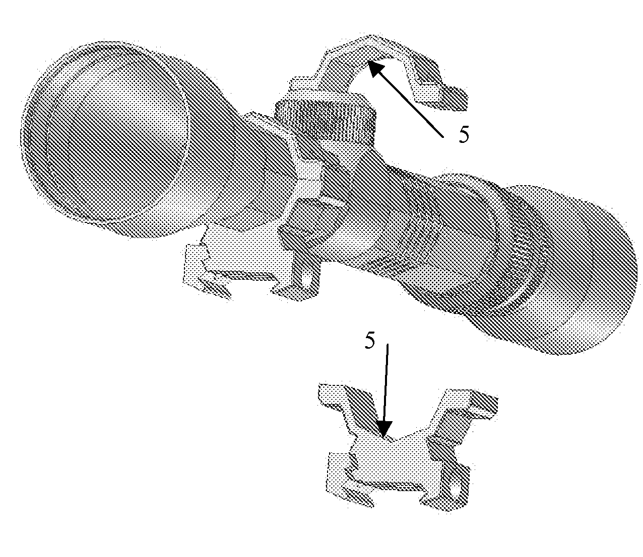
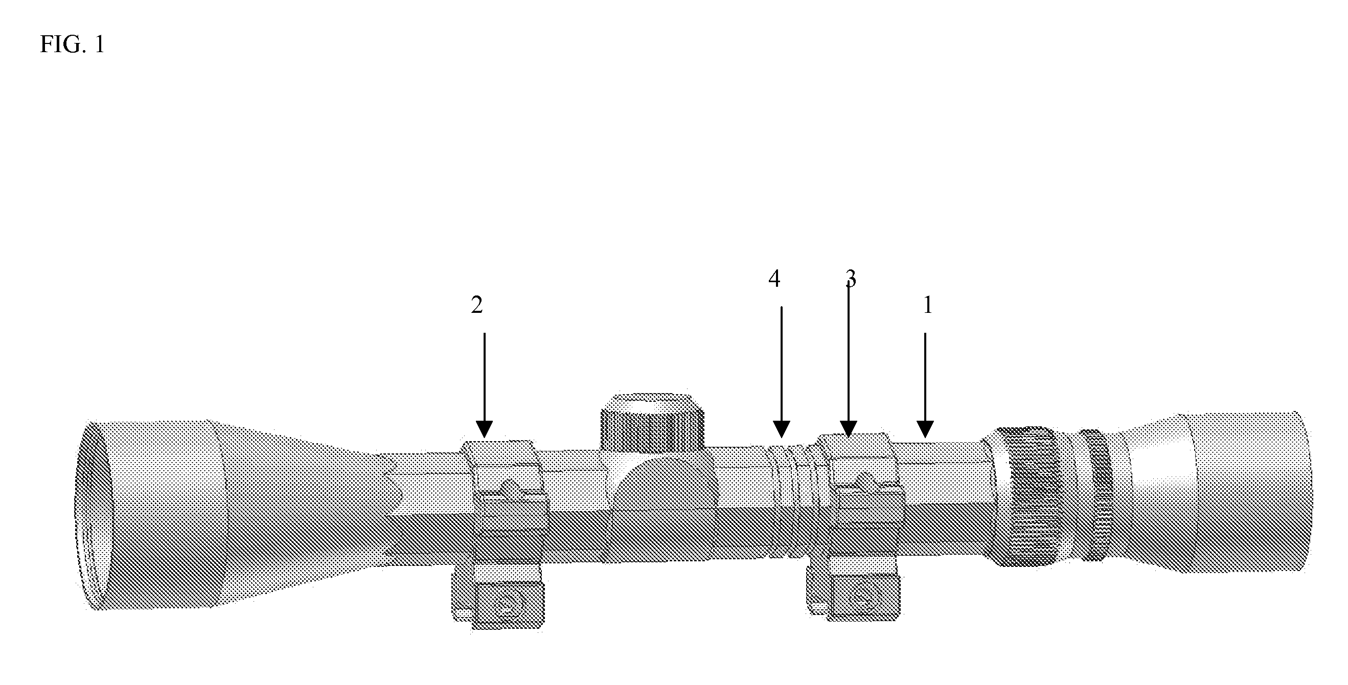
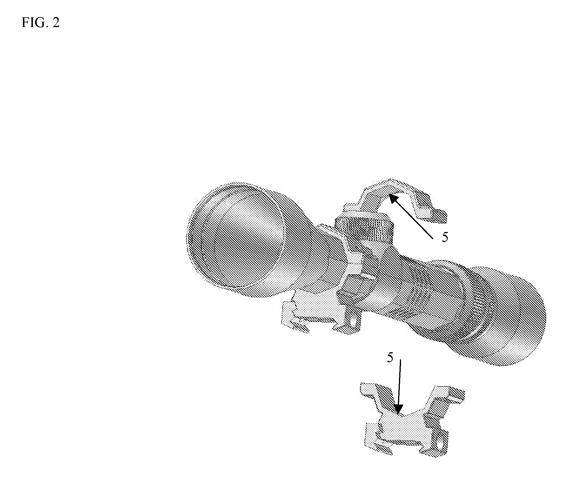
[0013]Shown in FIG. 1 is a scope (1) and its corresponding front ring (2) and back ring (3). The scope may be formed of octagonal or cylindrical tube stock and is formed with anindentation or indentations (4) as shown in FIG. 1. The indentations may be any shape but preferably circular or in the shape of crosses to aid in restricting movement in all axis. The indentations (4) mate with a corresponding scope ring (2) or (3), which has a complementary projecting key (5) located on its inner surface, as shown in FIG. 2, in the same shape as the plurality of indentations (4) for purposes of mating the key with the indentation. The indentations may be formed on any combination of the upper and lower portion of the front or back portion of the scope stock. The projecting key may be formed on the front (2) or back (3) scope ring or both of the corresponding scope rings, and located on either the top half of either ring or the bottom half of either ring or both halves. Furthermore, the inde...


PUM


Abstract

A telescopic scope and ring mounts incorporating a novel feature for locking the ring mounts to the scope to prevent canting and scope drift for secure and easy mounting on a gun.

Description

FIELD OF THE INVENTION[0001]This invention relates to the design and construction of a novel, scope and corresponding ring mounts for the improved accuracy and stability of scopes.BACKGROUND OF THE INVENTION[0002]Scopes, particularly those used for hunting, are well known in the prior art. Scopes are generally mounted to rifles or similar weapons and are used to assist hunters in aiming at desired targets. The prior art traditionally discloses the use of an externally smooth, cylindrical scope that is mounted to a rifle through the use of scope rings, which are traditionally smooth and cylindrical as well. However, there are several disadvantages attributable to using a scope and mounting device that are cylindrical.[0003]For example, a traditional smooth and cylindrical scope with a cylindrical mounting device is very difficult to align perfectly straight up and down so that the scope's reticle is not canted. When a scope's reticle is canted, the accuracy of the reticle's aim will ...

Claims


Application Information

Patent Timeline
31 Jan 2008
Publication
US20080022576A1
IPC
F41G1/38
CPC
F41G1/38; F41G11/001; F41G1/387
Inventors
EPLING, J. PATRICK