Systems and methods for selectively rotationally fixing a pedaled drivetrain

Active Publication Date: 2019-06-13
IFIT INC
View PDF6 Cites 34 Cited by
  • Summary
  • Abstract
  • Description
  • Claims
  • Application Information

AI Technical Summary

Benefits of technology

[0010]This Summary is provided to introduce a selection of concepts in a simplified form that are further described below in the Detailed Description. This Summary is not inten

Problems solved by technology

For example, “backpedaling” on a bicycle with a freewheel hub m

Method used


Image

  • Systems and methods for selectively rotationally fixing a pedaled drivetrain
  • Systems and methods for selectively rotationally fixing a pedaled drivetrain
  • Systems and methods for selectively rotationally fixing a pedaled drivetrain

Examples


Embodiment Construction

[0030]In some embodiments of a human-powered cycling system according to the present disclosure, a drivetrain may include a freewheel hub with a selectively actuatable locking mechanism to bypass the freewheel hub and create a direct drive linkage. As described herein, a lockable hub may provide additional training and / or propulsion options while increasing efficiency, safety, and enjoyment for a user.

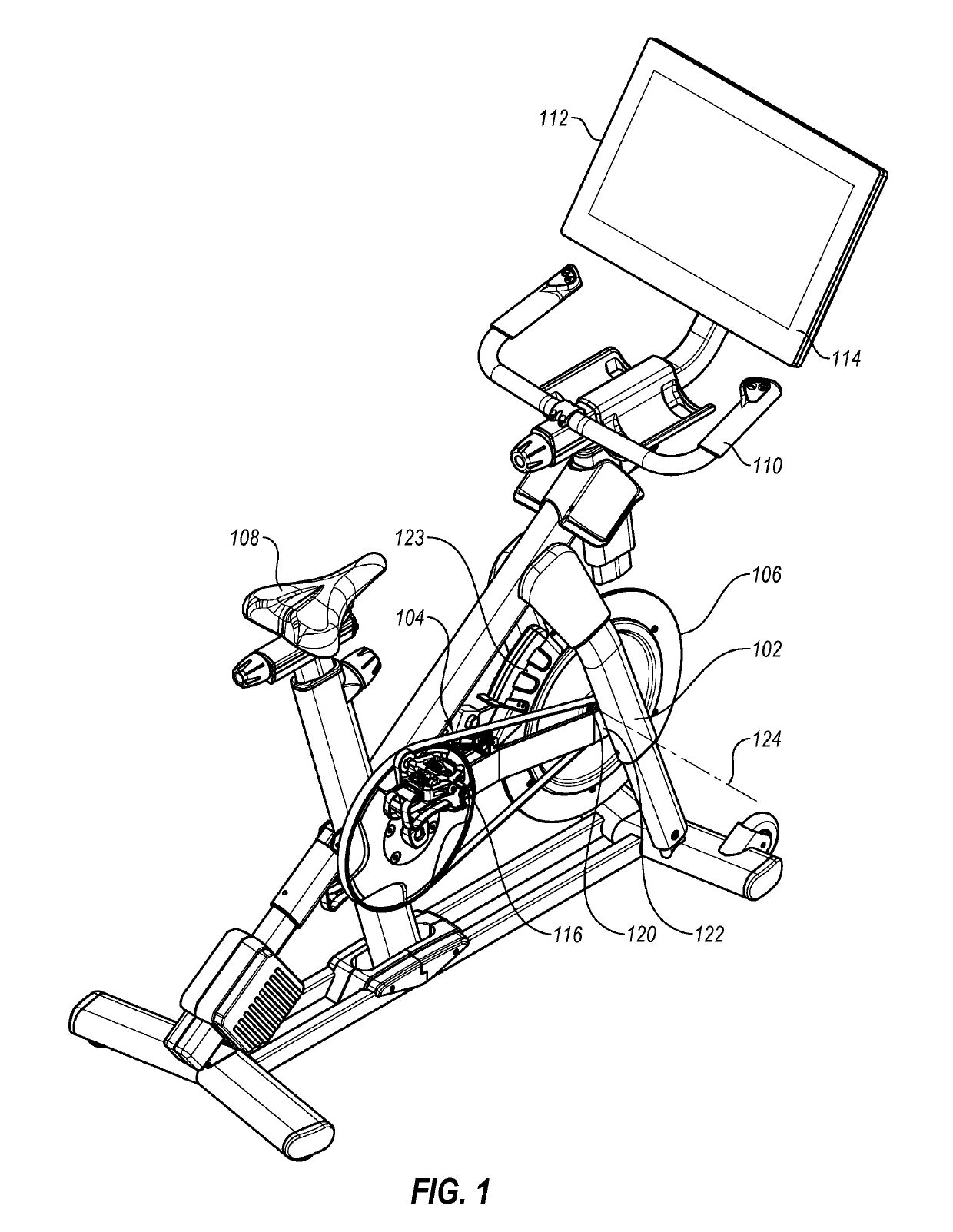
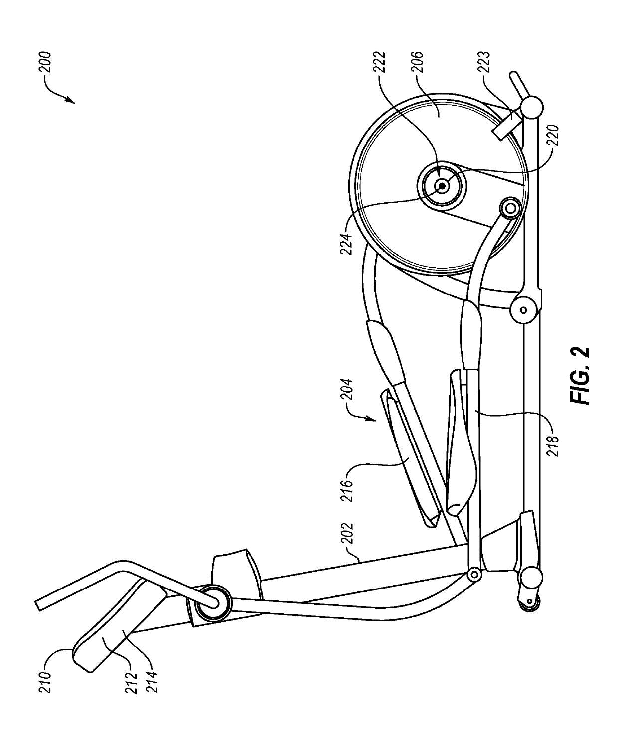
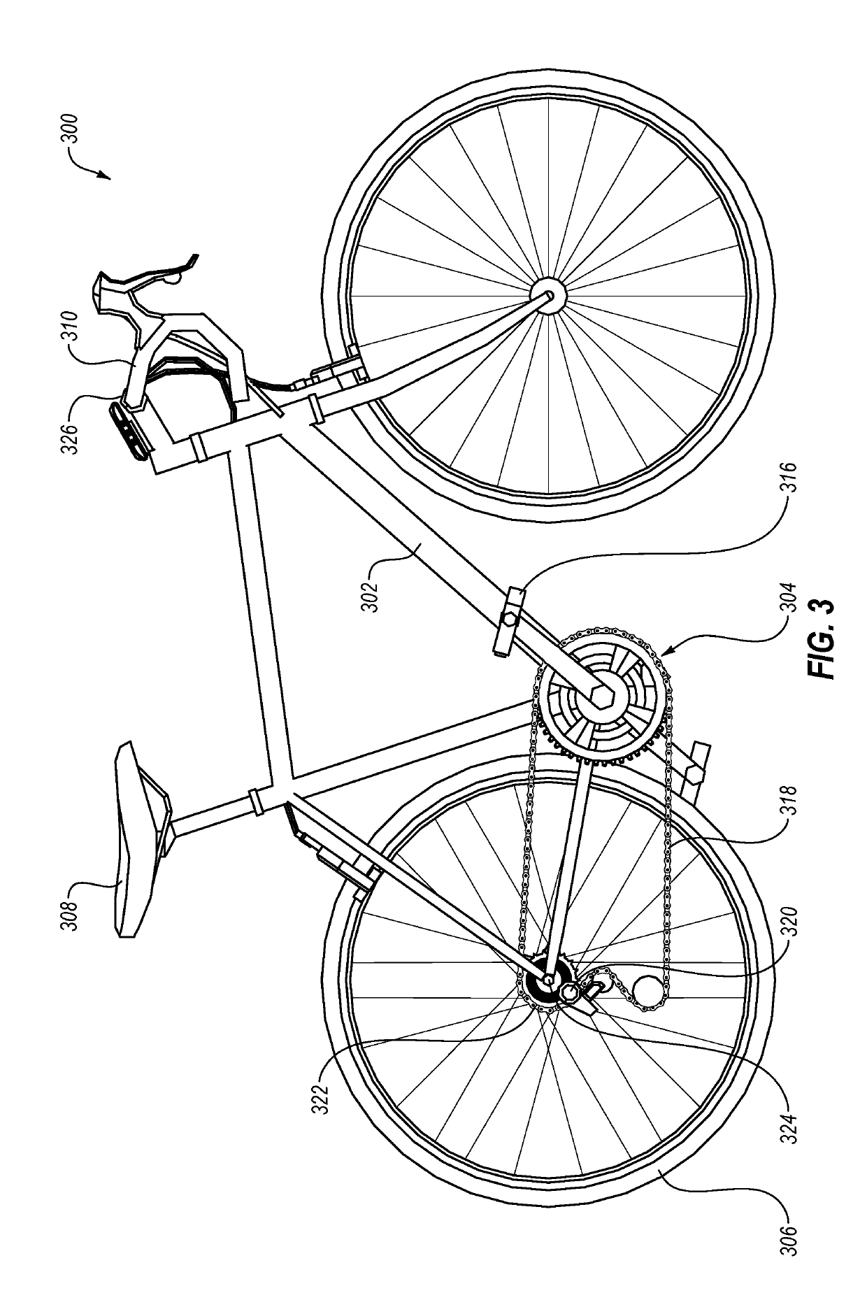
[0031]FIG. 1 through FIG. 3 are examples of human-powered cycling systems. Each receives a circular or elliptical input from a user, and may transmit that input to a wheel or flywheel in one or two rotational directions. FIG. 1 is a perspective view of an embodiment of an exercise bicycle 100, according to the present disclosure. The exercise bicycle 100 may include a frame 102 that supports a drivetrain 104 and at least one wheel 106. The frame 102 may further support a seat 108 for a user to sit upon, handlebars 110 for a user to grip, one or more displays 112, or combinations thereo...


PUM


Abstract

A pedaled drivetrain includes a drive mechanism, a wheel, a freewheel hub, and a locking mechanism. The wheel has a rotational axis. The freewheel hub connects the drive mechanism to the wheel, and the freewheel hub transmits torque from the drive mechanism to the wheel in a first rotational direction around the rotational axis. The locking mechanism has a locked state and an unlocked state. The locked state rotationally fixes a component of the drive mechanism to the wheel relative to the rotational axis.

Description

CROSS-REFERENCE TO RELATED APPLICATIONS[0001]This application claims priority to provisional patent application No. 62 / 596,815 entitled “SYSTEMS AND METHODS FOR SELECTIVELY ROTATIONALLY FIXING A PEDALED DRIVETRAIN” filed Dec. 9, 2017 and provisional patent application No. 62 / 609,718 entitled “SYSTEMS AND METHODS FOR SELECTIVELY ROTATIONALLY FIXING A PEDALED DRIVETRAIN” filed Dec. 22, 2017, which applications are herein incorporated by reference for all that they disclose.BACKGROUNDTechnical Field[0002]This disclosure generally relates to pedaled drivetrains. More particularly, this disclosure generally relates to selectively changing a pedaled drivetrain from transmission of torque in a first direction only to transmission of torque in both rotational directions.Background and Relevant Art[0003]Cyclic motion can be very efficient power output for transportation and / or movement and is used in bicycles, tricycles, and other land-based vehicles; pedal boats and other water vehicles; an...

Claims


Application Information

Patent Timeline
IPC IPC(8): F16D41/26B60B27/04F16D48/06
CPCF16D41/26B60B27/047F16D48/06F16D2300/24F16D2500/10406A63B69/16A63B22/0664A63B22/0605A63B22/04F16D11/14F16D41/30F16D41/04
Inventor WROBEL, DAVID
Owner IFIT INC
Why Eureka
Try Eureka